A detailed explanation of the Cocos Creator particle system. Zero code needed!
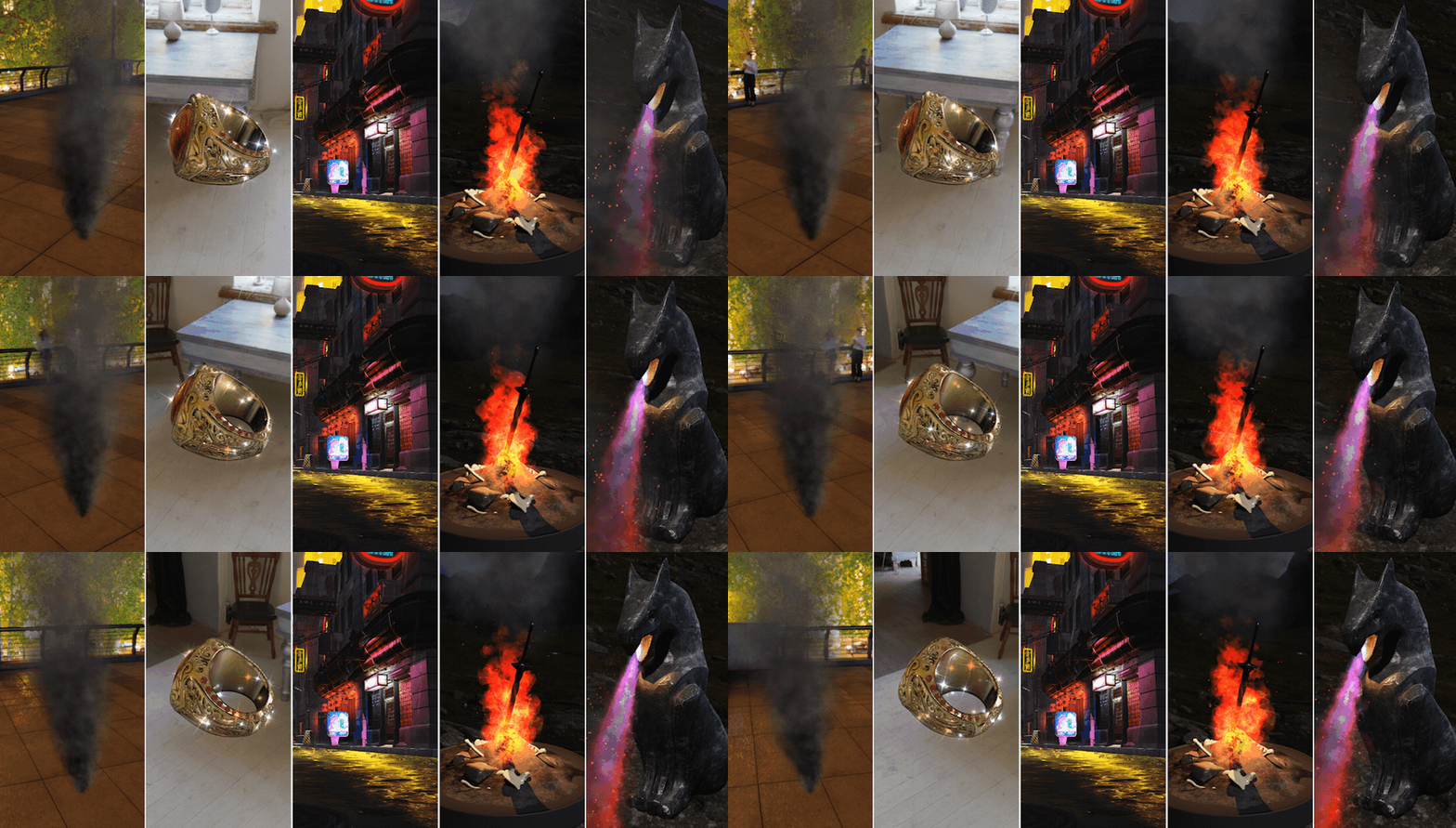
In the previous article, “Building a 3D outdoor scene with zero code”, we mainly introduced the construction of 3D outdoor scenes. In this article, we will understand the use of particle systems and the creation of some typical natural effects and the usual process of making a particle effect. This post will share how to:
-
Use a texture or model to determine the shape of each individual particle and create a corresponding particle material.
-
Create a particle system to determine the emission frequency, density, and flight speed of particles.
-
Use the dynamics module to add dynamic changes to simulate physical effects.
-
Move the particle system to a reasonable location in the scene.
Next, let’s start with the basics.
PS. This article will be divided into basics - smoke (normal particles) - performance optimization - starlight (animation particles) - rainfall (3D particles) - flames (composite particles) - fire and candle fire (variants of particles), and other several parts. The length of this post is long, and it is recommended to read what interests you first.
Basics
First, we need to create a new empty node in the scene: click the plus button in the upper left corner of the hierarchy manager, or right-click on any empty part of the hierarchy manager and select Create → Empty Node. Select the newly created empty node, click Add Component at the end of the property inspector, select Effects → ParticleSystem, and add a particle module to the empty node.
Particles are a rendering system that continuously emits renderable graphics outward from a fixed emission point. It is roughly composed of three main functional modules: emitter, particle, and renderer. Among them, we can control the position of the particles shot in the scene through the parameters of the emitter, the frequency and randomness of particle generation, the lifetime of each particle after it is shot, and so on. Through the particle-related function modules, we can control the change of each particle’s position, size, color, and other attributes after it is ejected. We can assign textures to each particle through the renderer, determine the blending mode of the particle system and the entire scene, the coordinate relationship between particles and the camera, and so on.
By default, the particle system will start producing particles as soon as it is activated in the scene. We don’t need any manual way to start it. When we select a node with a particle system, there will be preview control options for particle effects in the lower right corner of the scene editor, including start, pause, reset, stop, and playback speed. We can think of the particle system as a rendering system that generates animation by itself, and these preview controls are no different from the familiar animation control system. We can use them to control the preview effect of the particle system in the scene editor.
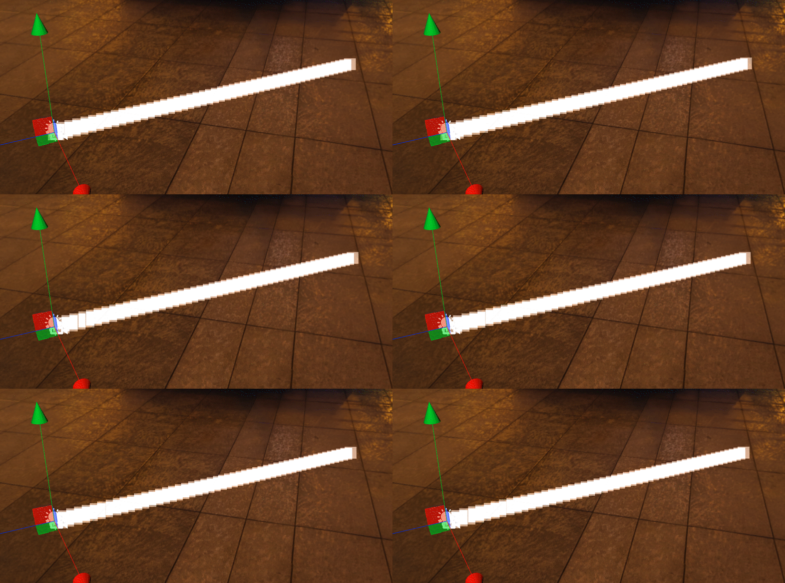
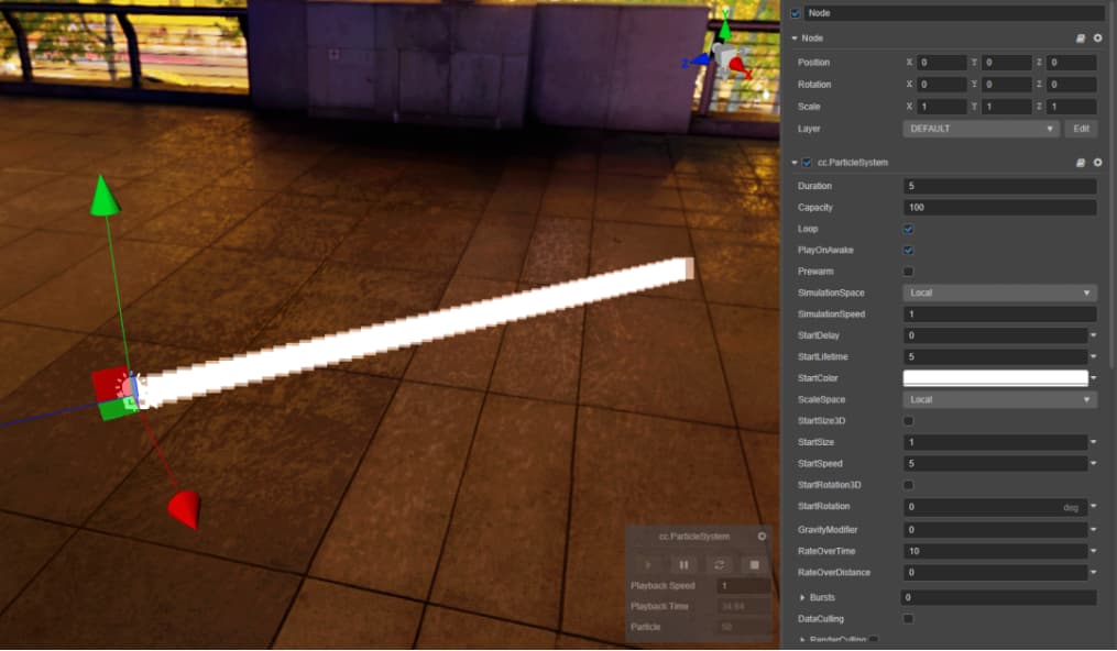
It can be seen that the default particle system will use the position of its parent node as the emission point and continuously emit a white translucent square shape in one direction. Because the emission frequency is high, the emitted particles do not have the slightest change in displacement and kinetic energy, so the emitted particles are connected into a white straight line. This is a far cry from the particle effects we imagined, and the first thing we have to do is figure out how the particles are emitted.
The current emission frequency is undoubtedly too high, so we first need to reduce the number of particles produced. With the particle system selected, change the parameter from 10 to 1 in the Property Inspector. Go to RateOverTime in the scene editor, and press the reset button on the bottom left playback control to re-render the particle system from scratch.
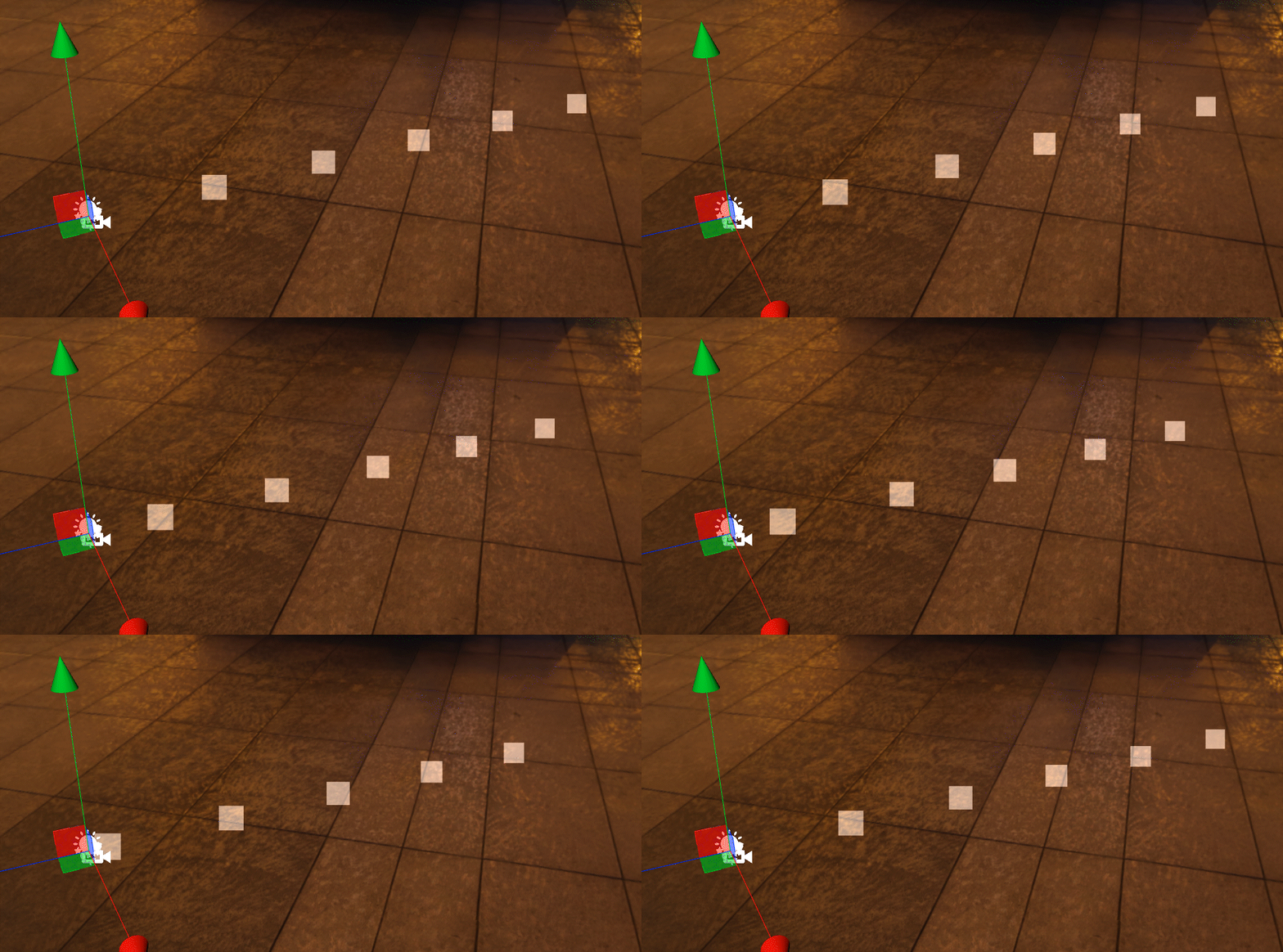
After the modification, the frequency of particle emission is much smaller. According to visual observation, it is about the frequency of emitting one particle per second. In addition, the maximum distance that the particles can travel has not changed. In other words: the length of the “straight line” formed by the particles connecting together has not changed. At present, the speed of a single particle is still too fast. We can try to change the StartSpeed parameter from 5 to 2.5.
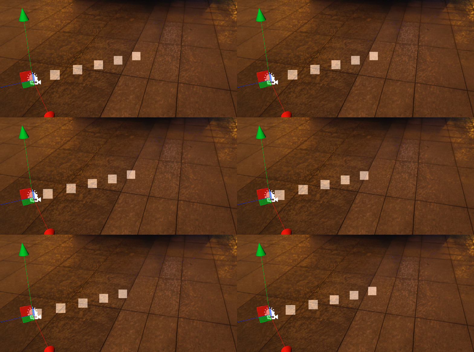
The flight speed of the particles is reduced by half. At the same time, the longest distance that the particles can travel is also reduced by half because the frequency of particle emission does not change, so the number of particles emitted in the same time period does not decrease. Accordingly, the distance between the front and rear particles is reduced.
Although the speed of particle flight is reduced, we still want to get the same maximum flight distance as before: we can change the StartLifetime parameter from 5 to 10.
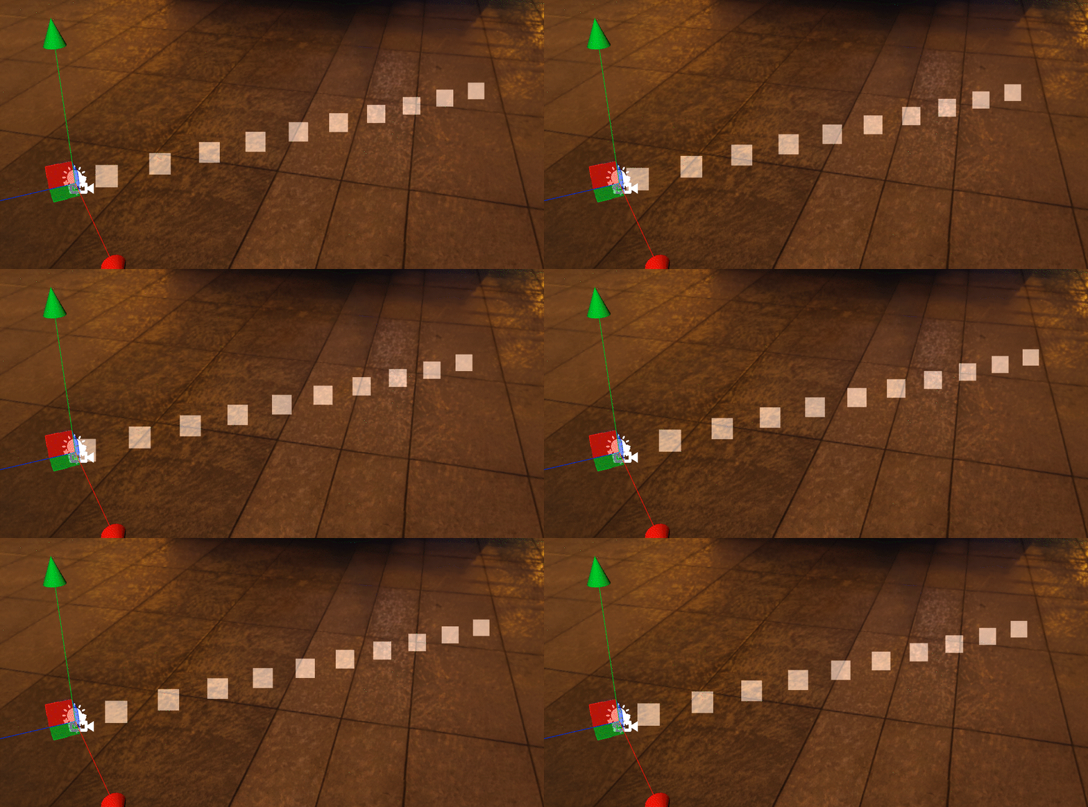
The maximum flying distance of particles is restored to its previous level. In contrast, the speed at which each particle travels and the distance between particles remain the same as we last modified. But there is a corresponding increase in the number of particles co-existing: from about 5, which we observed earlier, to about 10.
So what happens if you change StartSpeed from 2.5 back to the default 5?
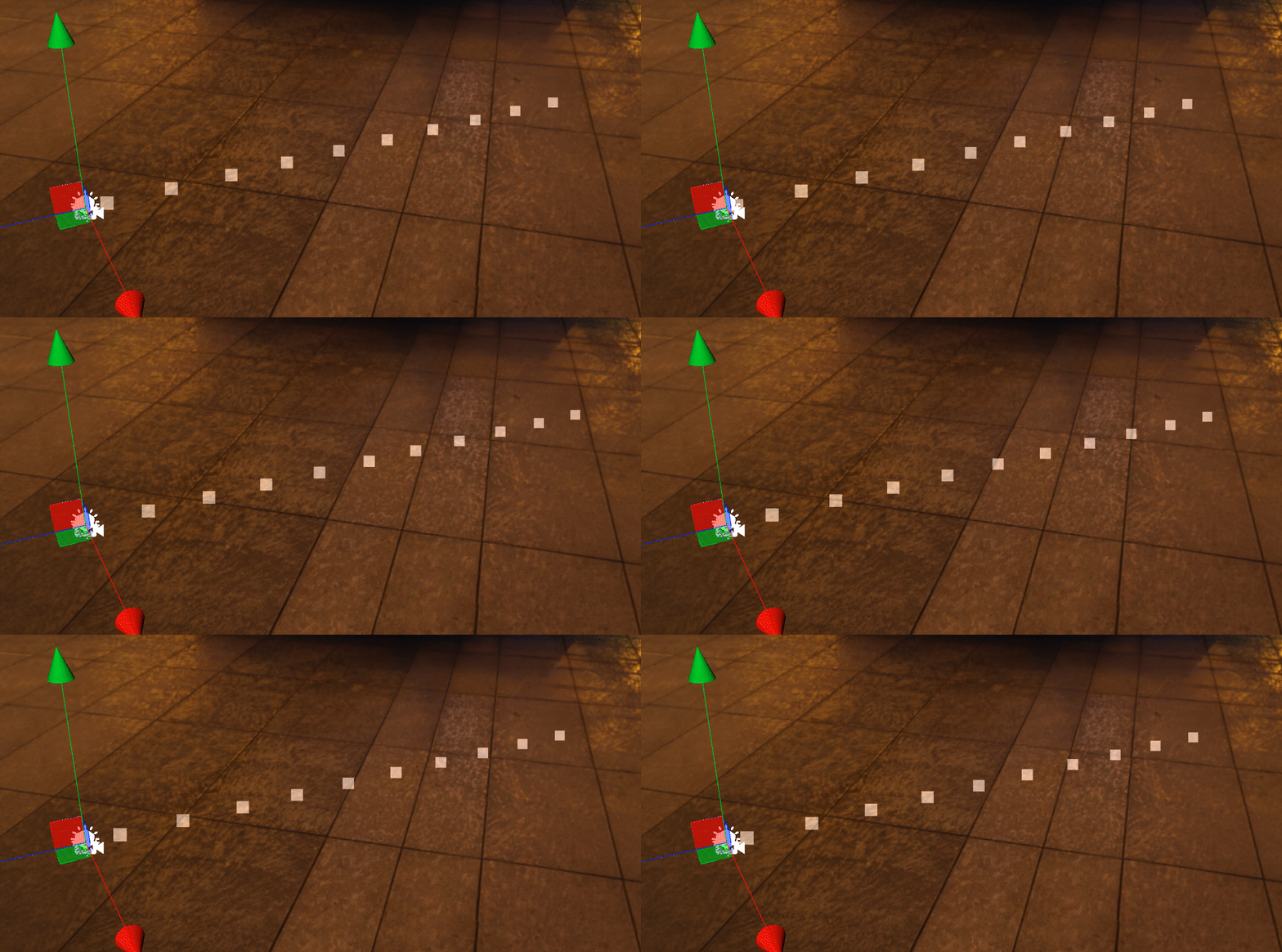
We can see from RateOverTime that StartLifetime still maintains a state of 10 total particles and are unchanged. But since StartSpeed is doubled, the distance the particles can travel has doubled in the same amount of time. In other words: the length of the lines connecting the particles have doubled.
To sum up, we seem to be able to observe specific laws between StartLifetime, RateOverTime, and StartSpeed. These three parameters are:
-
RateOverTime- Control the number of particles emitted per second. -
StartSpeed- Controls the speed at which particles fly after being emitted. -
StartLifetime- Controls the lifetime of a particle, which is how long a particle can exist after being emitted. The particles will automatically disappear from the scene when the life cycle ends.
Not only that, from the above experiments, we can also deduce these include the value of the number of particles that currently exist at the same time, how far a particle can fly, and the distance between two adjacent particles:
-
The number of particles that presently exist at the same time is roughly equal to the product of the number of particles emitted per second and the particle life cycle, namely
RateOverTime*StartLifetime; -
The maximum distance that a particle can fly is roughly equal to the product of the particle’s flying speed and the particle’s lifetime, namely
StartSpeed*StartLifetime. -
Decreasing the distance between two adjacent particles, or increasing the density of particles, increases the number of particles emitted per second (
RateOverTime) while keeping the maximum distance a particle can travel (StartSpeed*StartLifetime) constant and vice versa.
Having mastered these, we can use the maximum distance of particles to fly and the density of particles to control the overall shape of the particle system to a certain extent. In addition, we have been able to calculate the number of particles in the current particle system, which will help us maximize the performance of the particle system.
With a certain understanding of the emission principle of particles, we also need to give specific shapes to the particles. This white square is obviously not applicable anymore. We need to assign a specific material to the particle.
Click the plus button at the top left of the Explorer, or right-click in any blank area of the Explorer and select Create → Material to create a new empty material file. The particle system needs a shader specially prepared for it, so in the new material parameters, we need to select the Effect parameter as a builtin-particle.
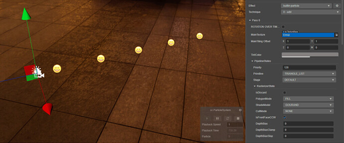
The particle material is straightforward. Just give the corresponding map to the MainTexture, then use the TintColor parameter to fine-tune the color and alpha. Save the changes to the material, go back to the particle properties inspector and drag the particle material to the ParticleMaterial parameter under the Renderer tab.
By default, the rendering method of the particle system is the same as the rendering method of the Billboard we mentioned earlier, which is to render the 2D pixels into the 3D scene in a way that always faces the camera. This setting we can choose in the RenderMode parameters. In the previous article, we mentioned that using a billboard with a gradient map to create the illusion of volumetric light can use the same method on particle systems: particle systems are often used to simulate smoke, fire, and flare effects. A flat texture to simulate the effect of a specific volume in reality. Therefore, Billboard is also the most common way to render particles. So, how are various effects in nature achieved using particle systems? Let’s start with smoke/fog.
Smoke (Normal Particles)
smoke final effect
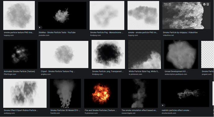
Since our goal is to make smoke, we first need a smoke texture material.
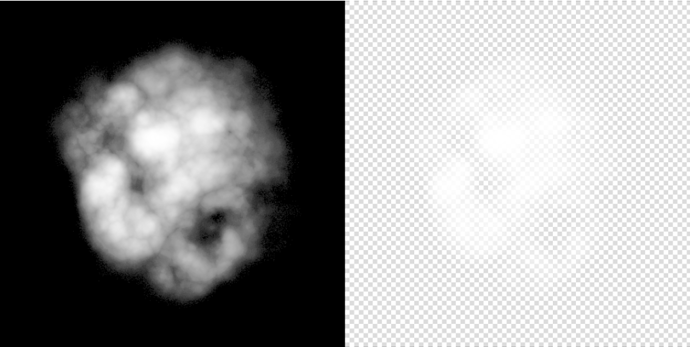
The lightness, color, etc., of the material doesn’t matter because we only need a part of the material. First, use a DCC such as Photoshop to remove the material’s color and only retain lightness information. Then adjust the levels to make sure the background is pure black. Save the material as a map, import it into the engine, and assign it to the newly created particle material.
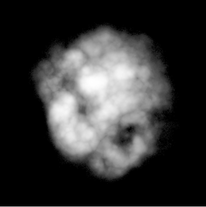
After using the smoke material, the original translucent square becomes a translucent texture patch, and a particular color is given to the texture through the TintColor parameter. Because of Billboard rendering, the patch always faces the camera. At first glance, It seems that there is indeed some meaning to a mass with volume.
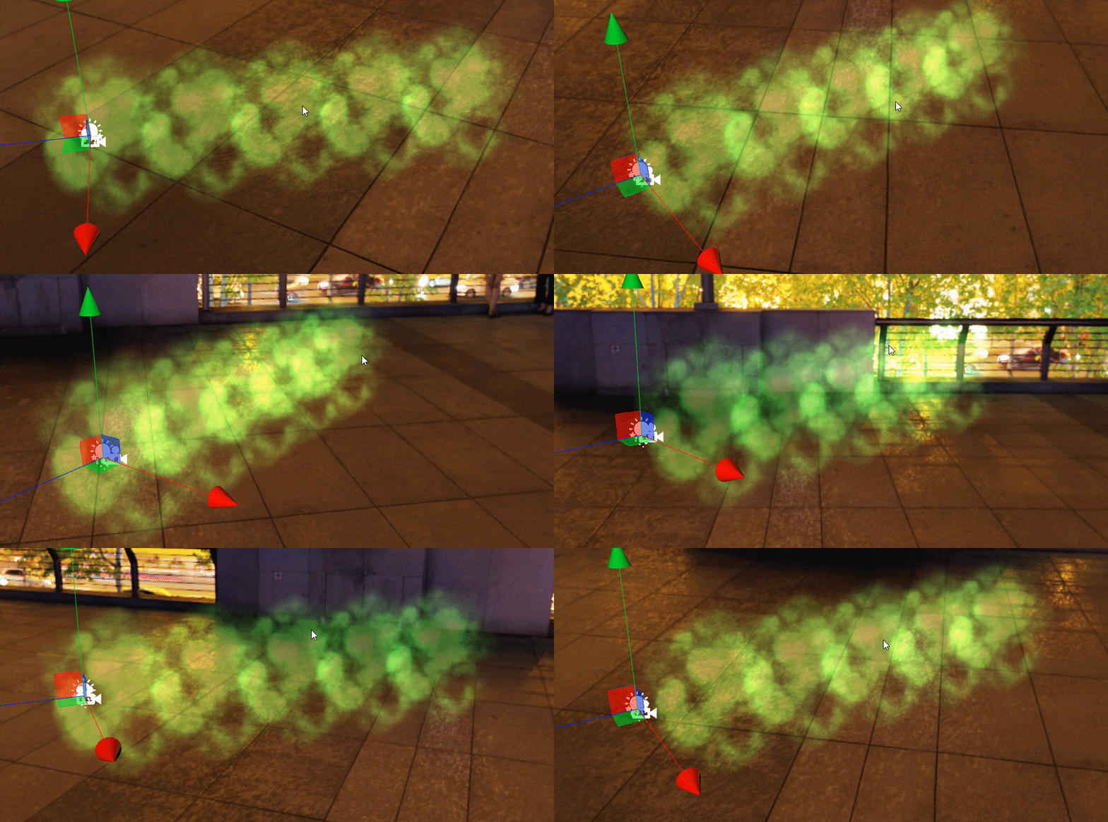
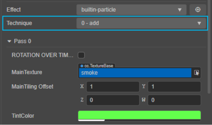
You have probably also discovered that the black background of the texture is not rendered, and there is an overlapping relationship between the texture patches. This is because the particle’s material uses the add alpha blending mode by default. The engine will use the brightness of the rendered particle pixel as the opacity and directly superimpose the particle pixel on the Frame Buffer in a linear addition manner. This effect is the same as choosing “Linear Dodge (Add)” in Photoshop. The alpha blending mode of the particle material is controlled by the Technique parameter.
In the default Add mode, the particle map used does not need to be transparent. Just make sure that the parts we want to be transparent are pure black on the map. Even a dark gray with very low brightness, which is not visible to the naked eye, will leave traces of the map edges in Add mode, leading to the problem of “unclean keying.” Similarly, we don’t need to include any color information in the opaque part because we can adjust the color directly through the material’s TintColor parameter. If the texture already contains color information, the particle material will produce a mixture of two colors, making it difficult to precisely control the particle color.
The Add mode seems to work fine, but there is a problem: what if we want to make black smoke? If you set the TintColor parameter to black, you will find that the particles disappear completely, this is because all the pixels of the texture are set to black and thus are regarded as completely transparent by the Add mode.
To fix this, we first need to modify the texture. Go back to Photoshop, copy all the black and white textures that have been made before, paste them as a new alpha channel, create a new pure white layer, select pixels from the new alpha channel and, generate a mask, save it as a format with an alpha channel (e.g., .png ).
Import the new texture into the engine and assign it to the particle material, and at the same time, select the Technique parameter to 1-alpha-blend. This mode is the opposite of the Add mode: only semi-transparent pixels are superimposed on the Frame Buffer, while opaque pixels retain their own color. So when using this blending mode, we need a map with an explicit alpha channel. Since the opaque pixel color is preserved, we can use black in the TintColor parameter, which won’t cause the particles to disappear.
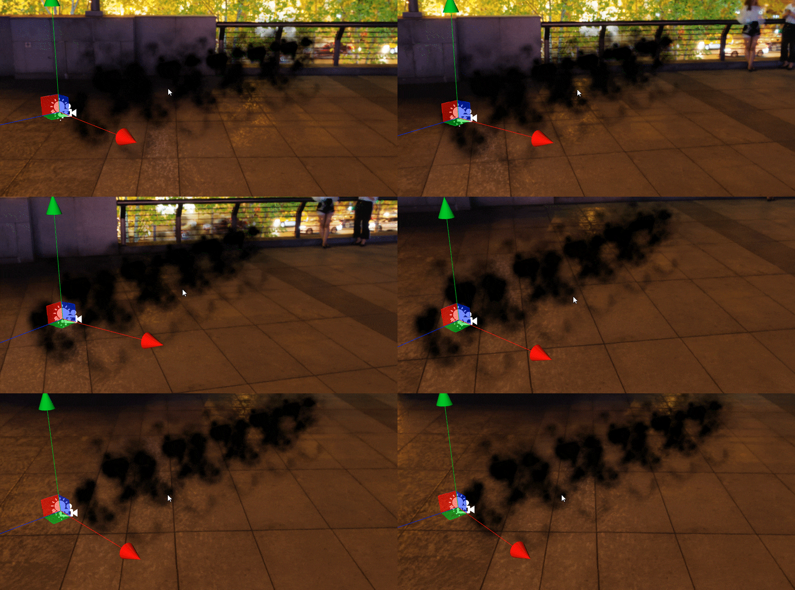
Now that our particles are “long” like smoke, what we need to do next is to use the dynamics module of the particle system to make the particles move more like smoke.
Currently, particle systems generate identical particles at a perfect uniform velocity, each moving horizontally at a perfect uniform velocity and disappearing at the same point in time. All we need to do is break out of this perfect state and insert some randomness into the particle system.
First of all, for smoke, the size of each particle can be larger. We can enter a larger value in the StartSize parameter to achieve this.
Larger particles can better reflect the volume of smoke, but at present, each particle is precisely the same. Can they have different rotation angles?
Use the StartRotation parameter to assign a rotation angle to the particles and enter a value. The result is that each particle changes the angle accordingly, and each particle is still precisely the same. Is it possible to give each particle a random rotation angle when generated?

Click on the inverted triangle at the end of the StartRotation parameter to get a menu of value types. The current selection is Constant, which means that the StartRotation parameter accepts only a constant value. By selecting TwoConstants in the menu, the StartRotation parameter changes, and we need to enter two values, ConstantMin and ConstantMax, i.e., a maximum and a minimum value.
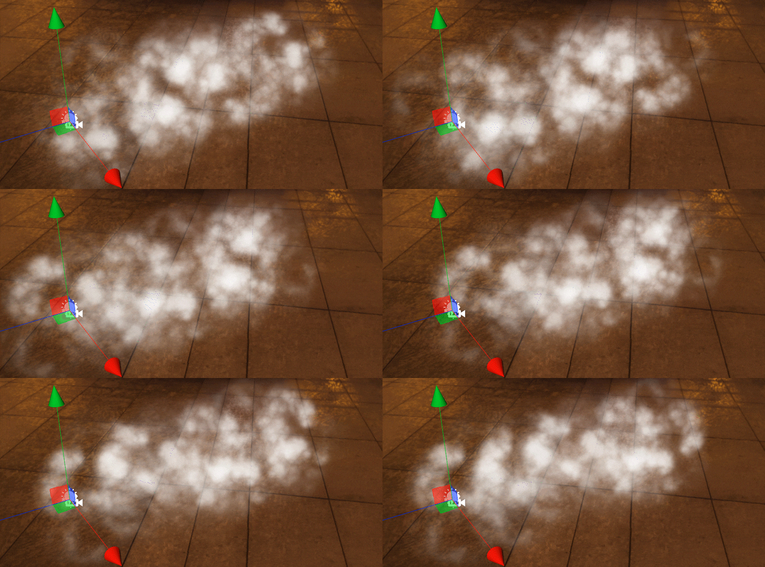
Now, each particle is given a random rotation value when it is generated, and this rotation value is determined by the interval between the maximum and minimum values that we define. Of course, the larger the value range of the interval, the greater the degree of randomness.
With this method, we can do the same, adding randomness to the particle size (StartSize), flight speed (StartSpeed), and lifetime (StartLifetime).
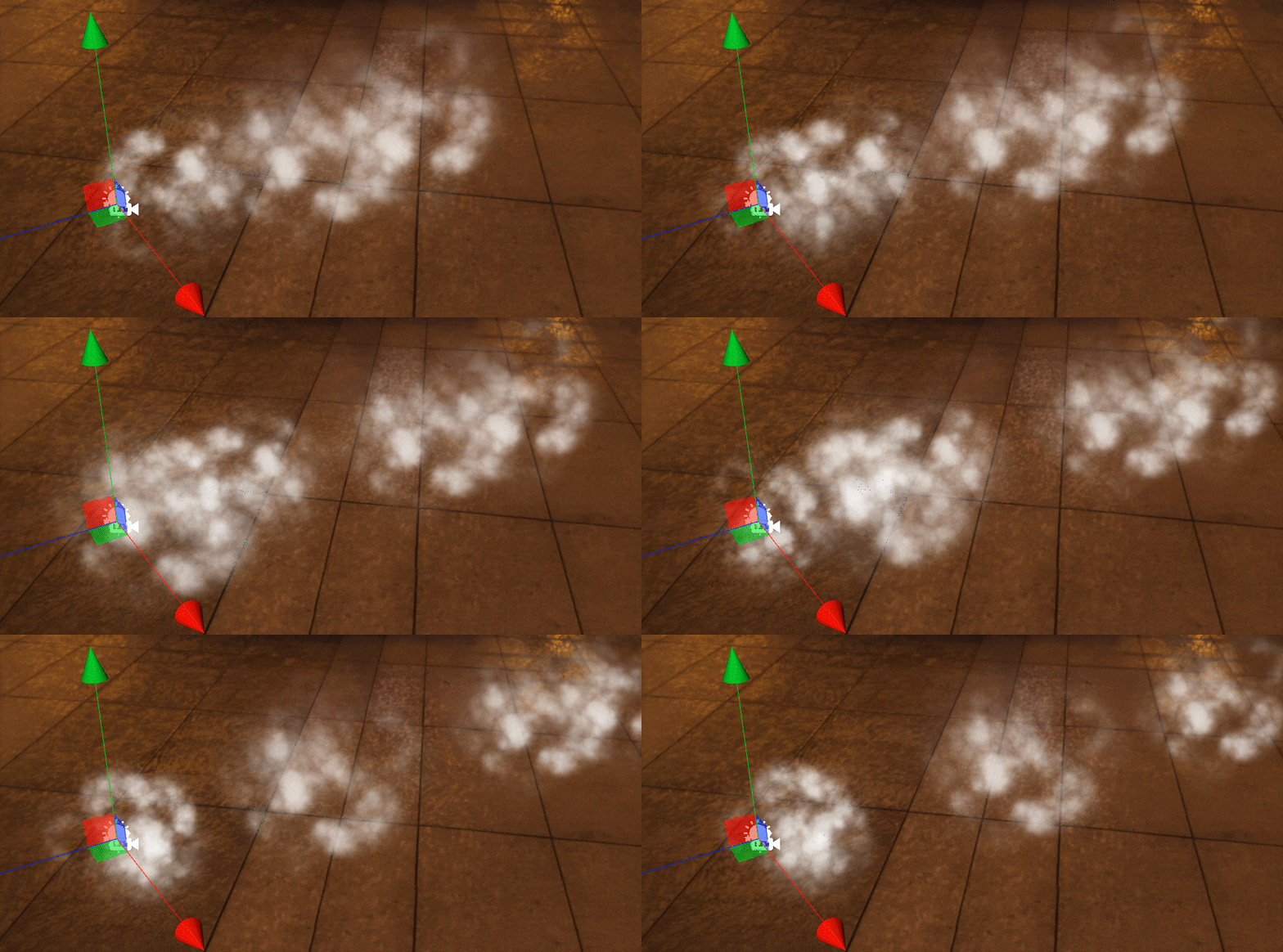
Now we have a bunch of particles with random rotations, varying sizes, flying speeds, and maximum distances. However, they look more like a few floating pieces of cotton rather than a single fluid. This is because the number of particles being generated is currently too low, and we need the feeling that more particles overlap each other.
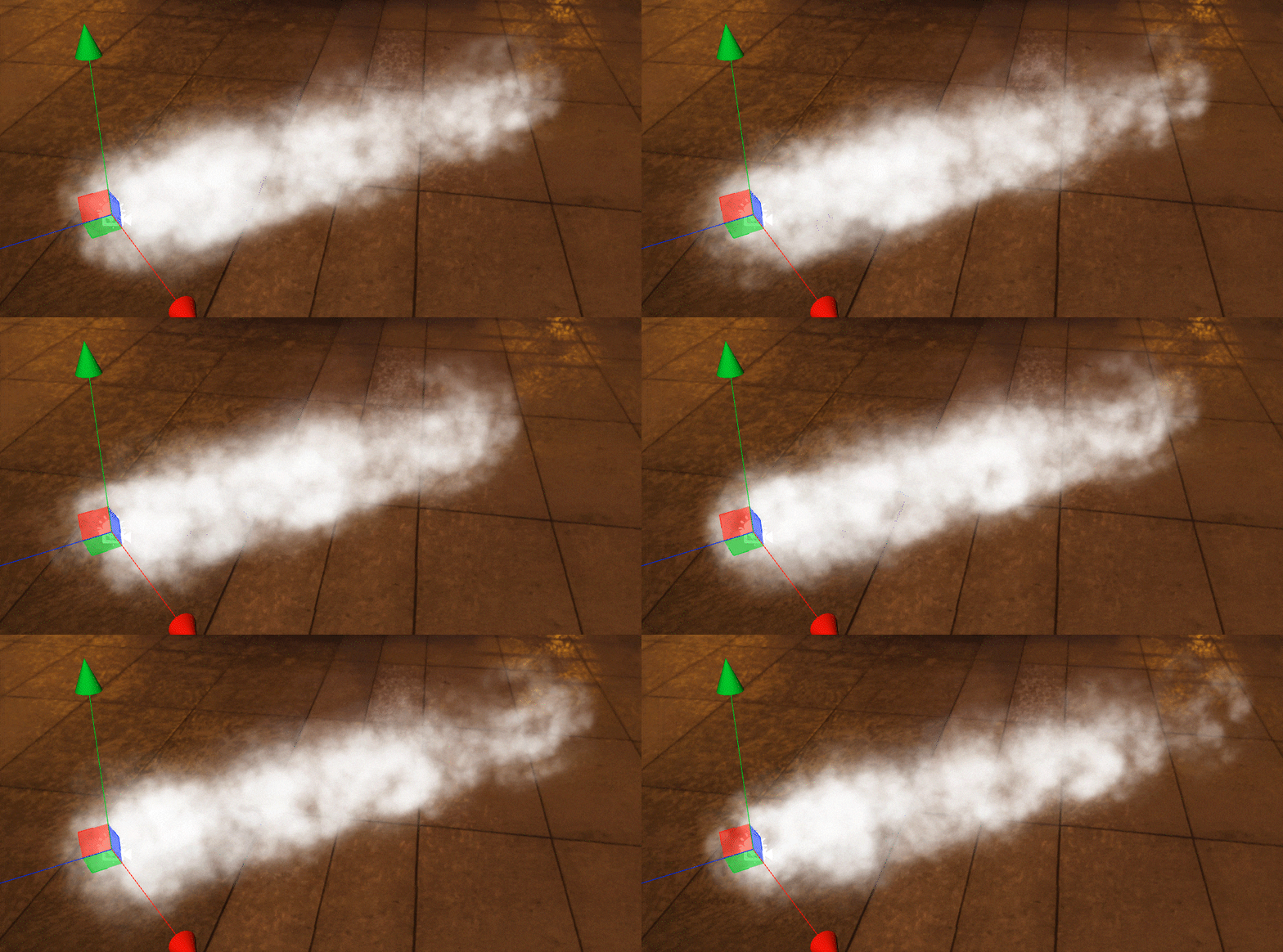
The effect of the smoke is close, but the particles are still emitted horizontally. Can we make the smoke float into the air?
We use an empty node as the parent node of the particle system at the beginning. It is, of course, feasible to achieve a vertical particle emission direction by rotating this node, but doing so will change the world coordinate system of the particle, which is easy when the particle system is more complex — A confusion of directions.
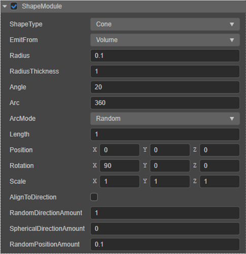
Several modules can be checked under the property inspector of the particle system. Checking ShapeModule will enable the parameter settings related to the transmitter.
Particle emitters are divided into five shapes: box, circle, cone, sphere, and hemisphere. They determine the range and direction of particle emission. Particle emission can only occur within the scope of the emitter. We can combine particles with different models and takes advantage of the characteristics of varying emitter shapes to ensure that particles don’t go where they shouldn’t be.
Emitters contain parameters for position, rotation, and scale, which can change the position and orientation of the emitter in the scene without affecting the alignment of the entire particle’s coordinate system to world coordinates. RandomDirectionAmount and RandomPositionAmount can add certain randomness to the direction and position of particle emission based on the emitter. The SphericalDirectionAmount parameter allows particles to increase the random probability of being emitted in all directions around them without ignoring the emitter.
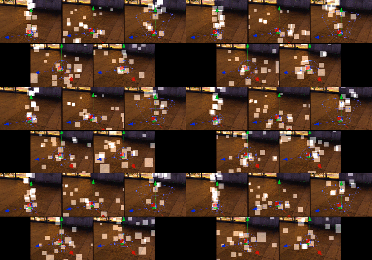
Just rotate the emitter 90 degrees along the X-axis to change the direction of particle emission.
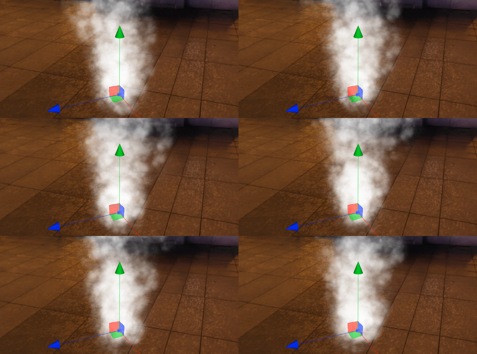
The overall effect now looks acceptable, but each particle is rigid in the process of flying. If you observe it alone, you can still see the feeling of the texture.
In addition to adding randomness to the particle’s emission, we can also add dynamic changes to the particle’s flight after it is launched.

Check to RotationOvertimeModule and enable this module. The function of this module is to make each particle rotate according to a certain angle every second during the flight. Of course, it is also possible to assign a range of random values to its parameters so that each particle rotates slightly differently.
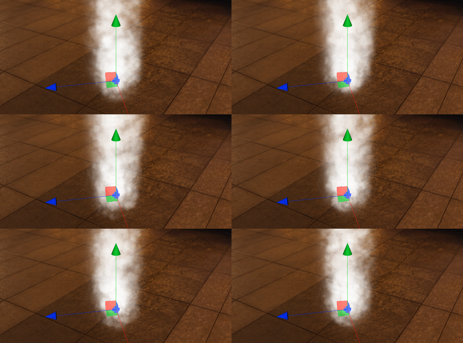
After adding the dynamic change of rotation, the 2D look and feel of the texture is further weakened. The rotation of the particles can also simulate the feeling of gas evaporation.
The processing of the individual particles is almost done. We still need to consider the behavior of the whole particle system or the whole column of smoke.
The column is now the same size from top to bottom. In other words: the particle is one size from birth until the end of its life cycle. This effect is obviously unnatural, especially when we want to create the effect of smoke coming out of a small outlet.
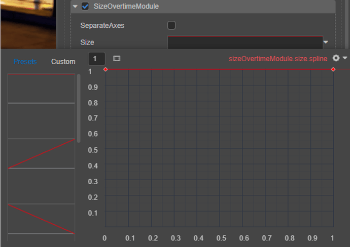
Check SizeOvertimeModule to enable this module. The difference with RotationOvertimeModule is that this module’s parameters only make each particle StartSize scale by a specific value multiple according to the size that has been set. Even if it is given a maximum value and a minimum value, each particle will be randomly scaled in the interval. The problem of the overall size of the smoke column has not been solved. At this point, we need to call two other numeric types: Curve and TwoCurves.
Select Curve and click the input box of the parameter to pop up the curve editing window.
The numerical relationship of the curve is easy to understand: The horizontal axis of the curve represents the time, that is, the life cycle of a single particle; the vertical axis of the curve represents the value, since we are modifying SizeOvertimeModulethe value, the horizontal axis, of course, represents the multiple of the size scaling. By default, the curve is a horizontal line, which has the same effect as if we entered a constant value: the particles use the same scaling factor from birth to the end of their lifetime. Our goal is a large plume at the top and a small plume at the bottom. Translate this logic with curves: we want a curve that goes “all the way uphill” from left to right.
Under the Preset tab on the left side of the curve editing window, we can quickly select a curve that meets our requirements, the simplest of which is a straight line from (0, 0) to (1 1). Of course, the effect it produces is a linear increase in the size of the particles from new to old, forming a nearly conical column of smoke.
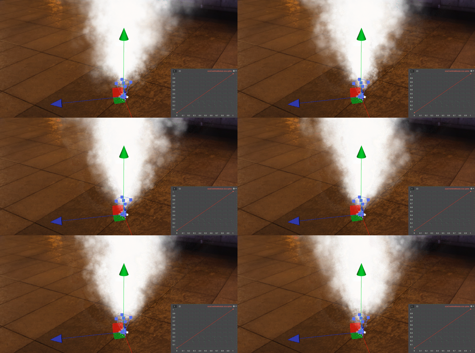
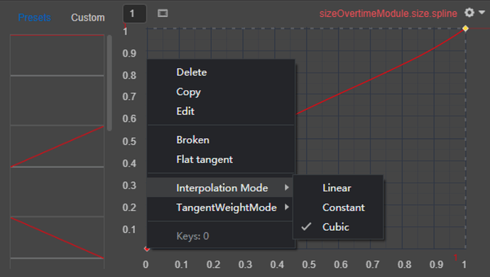
Although a linear curve is probably acceptable, we can also fine-tune the model based on the curve for a more natural effect. Click any anchor point on the curve to drag the position of the anchor point on the curve, right-click on the anchor point, select Interpolation Mode → Cubic to change the interpolation mode of the curve, and use the Bezier curve to generate smooth values over.
Right-click any part of the curve segment, select Create keyframe, insert a new anchor point on the curve, right-click on the anchor point, and select Edit. You can manually input the coordinate value of the anchor point and click the anchor point to complete the input and confirm.
Finally, right-click on the anchor point and select Delete to delete the anchor point.
Now that you are familiar with these operations, we can use curves to create various parametric animation effects. To put it simply, these parameter animations are for each individual particle, and the duration of the animation is the life cycle of the particle. If your particle life cycle is short, no matter how complicated these parameter animations are, they will pass accordingly in an instant.
Now that we have seen the curve value types, let’s test you before continuing the following content. We introduced you to RotationOvertimeModule before, but what will happen if we enter curve values in RotationOvertimeModule?
As we mentioned, the function of the RotationOvertimeModule is to make each particle rotate at a certain angle per second during its flight. So its parameter value is actually equivalent to the speed of rotation rather than the displacement value, so if we give it a curved value, it will appear that the particles rotate faster and faster or slower and slower as they go through their life cycle.
Now that we have the “shape” of the column, we still need to deal with the “state” of the column. A straight column of smoke in real life is almost non-existent, and the column will be deflected to some extent by the airflow.
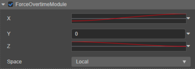
We can use ForceOvertimeModule to add a force effect to the particles in flight. Although the smoke uses 2D textures, the particles are emitted in 3D space, so you can also apply forces to the particles from the three axes of x, y, and z. Likewise, we can use curve values instead of constant values to add dynamic changes to it.
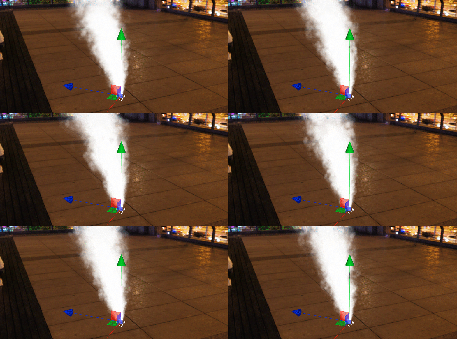
Doing this, we finally have the last module of the smoke, and probably the most important one: the color change.
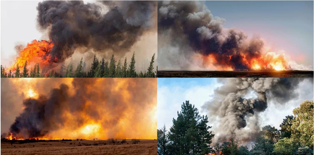
Let’s first observe a few reference pictures: According to the different burning impurities, the thick smoke produced by the flame is darker when close to the flame, close to a black color, and slowly turns into dark gray and light gray as the smoke drifts, until it disappears completely.
We have previously implemented different colors of smoke using the TintColor parameters. However, what needs to be adjusted now is the overall color change of the smoke column. The modification TintColor will only use all particles indiscriminately, so pure white is still used in the particle material.
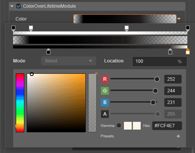
Check ColorOverLifetimeModule to enable this module. This module is very similar to the modules we touched on before. Its parameters receive a constant color by default. Using a constant color has the same effect as changing the color of the particle material and will produce a smoke column with all particles dyed indiscriminately. ColorOverLifetimeModule can also receive two constant colors (TwoColors), different from TwoConstants we touched on earlier. Each particle will randomly choose a color between the two constant colors, forming a mottled smoke column. We’re going to use today the third numeric type, Gradient.
Click the parameter input box to pop up the color gradient editing window.
The color gradient is the same as the logic of the curve we touched before. From left to right, the entire length of the gradient is equivalent to the whole life cycle of the particle, and the Alpha and color on the gradient are comparable to the alpha and the color that the particle should have in the corresponding life cycle. The editing of color gradients is very intuitive, and it is the same as making color gradients in Photoshop: the upper slider controls the alpha value. You can click any part of the slider to generate a new node, select the node, and give it an Alpha value in the lower color selector. The slider below controls the RGB value. Similarly, click any part to generate a node and assign an RGB value.
Currently, the particles do not have any gradual fading in and fading out effect when generated and disappearing. Since SizeOvertimeModule has little effect, this abrupt disappearance dramatically affects the look and feel when the particle disappears.
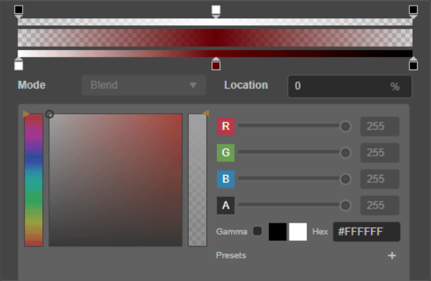
ColorOverLifetimeModule is very suitable for solving this problem. We only need to create a color gradient with an alpha value of 0 at the head and tail so that the particles that have just been emitted and are about to disappear become fully transparent, leaving only the central part in the middle. On this basis, according to the color changes observed in the reference image, we can create several gray nodes of different lightness on the gradient to create a color change effect from dark to light.
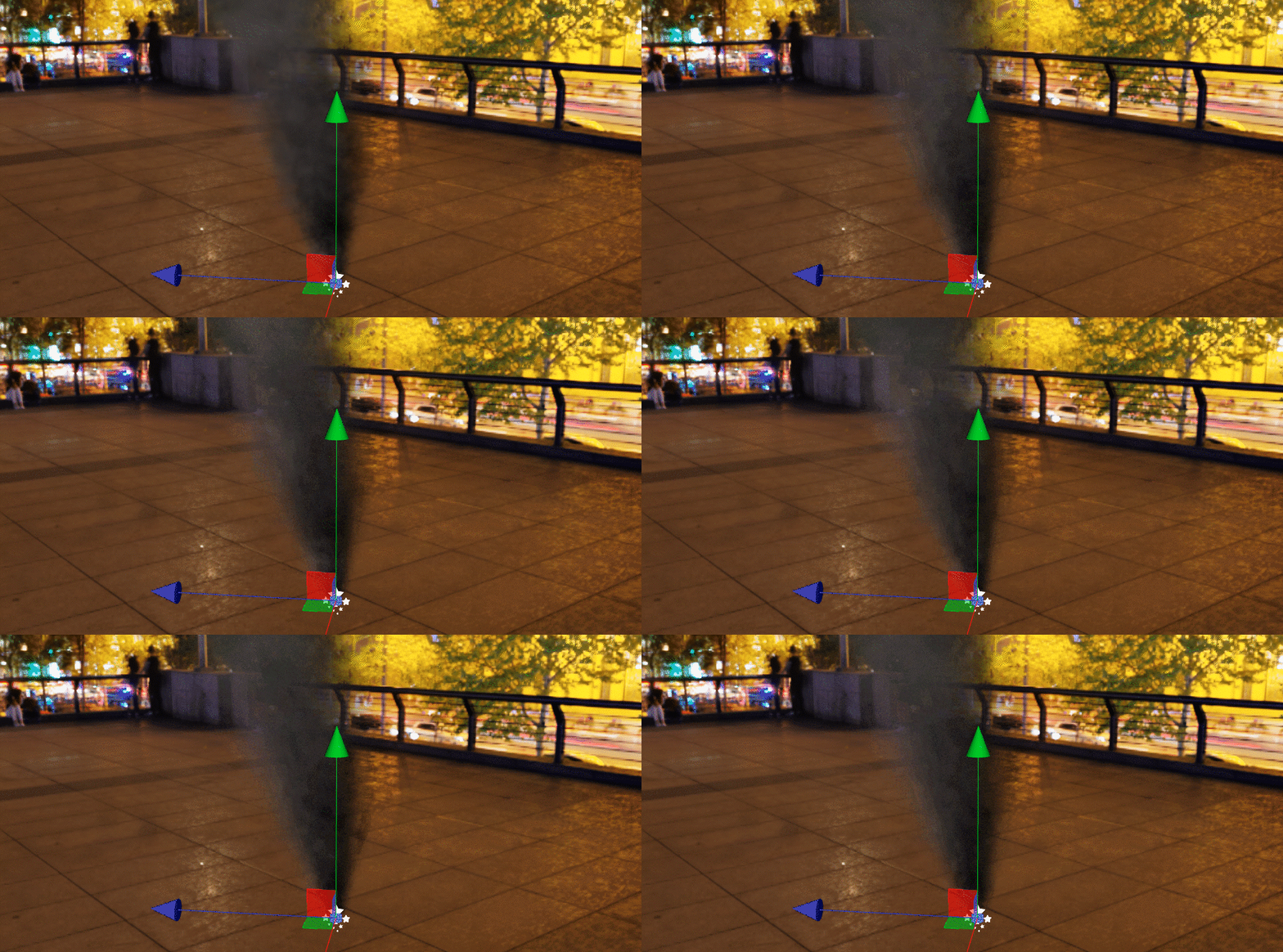
Having done this, the smoke column is now shaped. Before we end the production, we finally fine-tune the parameters once according to the details. After the above process, I believe you are familiar with the parameters that need to be adjusted to achieve different effects:
-
Is the smoke flying too fast or too slow? adjust
StartSpeed -
Is the plume too high or too low? Based on the
StartSpeed, adjustStartLifetime -
Is the smoke too thin or too thick? Adjust the RateOverTime to determine the
StartSpeedandStartLifetime. Also, adjust the alpha value of the particle materialTintColor -
Is smoke coming out in all directions indiscriminately? Adjust
ShapeModule -
Is the plume too thin or too loose? adjust
SizeOvertimeModule -
Does the smoke look too rigid or messy? adjust
RotationOvertimeModule; -
Is the smoke drifting in the wrong direction? adjust
ForceOvertimeModule; -
The color of the smoke is not rich enough? adjust
ColorOverLifetimeModule.
Performance optimization
The most significant factor affecting the performance of the particle system is undoubtedly the number of particles on the screen at the same time. Just looking at our current smoke particles makes little sense for the performance impact it might have. But if it is a particle system with a massive number of particles, the flight trajectory is very complex, and each particle is a particle system of a 3D model. The performance impact is difficult to ignore.
The most significant impact is on the Capacity parameter for the number of particles on the same screen simultaneously. Its function logic is: when the number of particles that exist in the particle system at the same time is higher than the Capacity’s specified value, the particle system will temporarily stop emitting particles and wait for the end of the current particle life cycle until the current number of particles drops below the Capacity value, and then the particle emission will resume as normal. So when we turn up the RateOverTime parameter to a certain level, there will be a “stutter” of particle emission, which is precisely when the Capacity parameter comes into play.
Therefore, to obtain the best performance and reduce the frequency of particle emission (RateOverTime) so the effect is acceptable, we also need to control the number of particles (Capacity) that can exist at the same time to the minimum range.
Fortunately, the number of particles that exist at the same time can be calculated by RateOverTime * StartLifetime. Therefore, we only need to take a value slightly larger than RateOverTime * StartLifetime to ensure that Capacity will not cause the particle to suspend emission to ensure the execution of the particle system runs smoothly without affecting the effect.
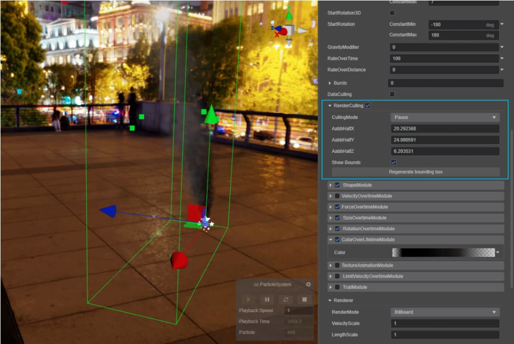
In addition, we can also open the RenderCulling function of the particle system by checking RenderCulling and pressing Generate bounding box. The engine will form a bounding box based on the area the particles may fly to. When RenderCulling is turned on, if the bounding box does not appear in the observable range of the camera, the entire particle system will not be rendered. When the bounding box returns to the camera’s field of view, particle rendering will be turned on again. The size of the bounding box can be adjusted manually through parameters. Turning on RenderCulling can avoid consuming meaningless rendering resources when the particles are not observed.
Starlight (animated particles)
starlight final effect
Our first particle system has been completed. With the realization of the smoke effect, we are already familiar with the basic logic of the Cocos Creator particle system and the method of general effect creation. For smoke, the key to the effect lies in the rendering method of the particles and the dynamic change relationship. Each individual particle is actually just a static map, and the static map is completely unchanged.
Of course, static maps can’t meet all our needs for particle effects. What if each individual particle needs to be animated?
Billboard’s rendering method is ideal for merging 2D textures as particles into a 3D scene. We can use the same method to import dynamic textures into the engine for use by particle systems, so the question is: how to import dynamic textures into the engine?
Whether video format or a .gif file, it is essentially a collection of static pixel images of many frames. A dynamic picture effect is formed when the program plays these pixel images in sequence at a certain speed. In the field of post-production special effects, the image sequence is still a commonly used tool. The so-called image sequence is to render each frame of an animation or video as a static picture in a specific format for recombination and playback in a DCC. At present, most mainstream video editing software, post-processing software, and 3D design software support rendering image sequences.
Image sequences often generate a large number of image files. For example, a 1-minute video played at 30 FPS at 1K resolution (1920 × 1080) would export 1800 individual images, a total amount of data more significant than any video file of the exact resolution and frame rate. Game engines are often very sensitive to the Capacity of resources, and image sequences are clearly not going to work.
In the field of 2D games, we have come into contact with the concept of Sprite Sheet. The Sprite Sheet is similar to the image sequence. It also stores each frame of the animation as a static image. The difference is that the Sprite Sheet will Assemble all still images into the same texture. Unfortunately, very few DCCs on the market support the export of sprite atlas for direct use by artists, except for Adobe Animate. So, if you can convert an image sequence into a sprite atlas, will it open the door to a new world?
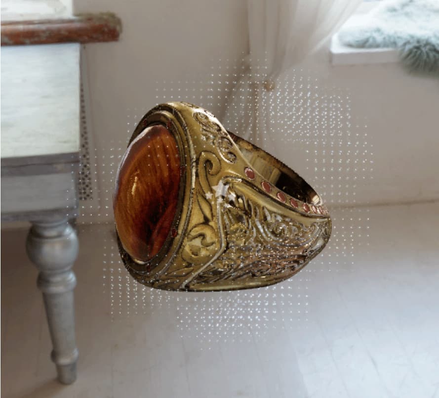
Let’s take a look at the process of importing starlights as particles into Cocos Creator.

The starlight effect was created using the Red Giant plugin in After Effects, this simple flickering animation is 2 seconds long, and the frame rate is 30 FPS. The first thing we will do is export it as an image sequence. (Search on how to do that on YouTube)
After rendering is complete, the images contained in the image sequence can be found in the directory you chose. All that needs to be done is combine these images into a single map.
Granted, we could open Photoshop and manually drag them together on a large enough canvas. However, this operation is time-consuming and labor-intensive, and if you encounter an animation with a more significant number of frames and a longer duration, the number of pictures in the image sequence will increase accordingly, and manual dragging will not work.
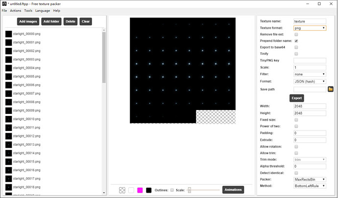
Here we use Free Texture Packer, a free software, to help us complete the stacking of pictures. Free Texture Packer is a sprite atlas generation tool specially designed for game engines such as Cocos, Unreal Engine, Phaser, etc. It provides cross-platform support and is entirely open-source.
Download Free Texture Packer:
After downloading and installing, open it directly, click Add Images, and select all images in the image sequence to import.
Slide the Scale slider to see a preview of the stacked sprite atlas. You can enter the relevant parameters for generating the sprite atlas in the property bar on the right. To correctly apply to the particle system, the following parameter settings need to be made:
• Set Packer to MaxRectsBin
• Set Method to BottomLeftRule
• Do not tick Detect identical
• Do not tick Allow rotation
• Do not tick Allow trim
• Padding and Extrude both are 0
Enter the ideal resolution size of the sprite atlas in the Width and Height parameters. If there are too many pictures in the currently imported image sequence, a sprite atlas may not fit, and the software will automatically put the parts that cannot fit into it into a second set of pictures. This is, of course, not the result we want. Adjust the values of Width and Height, try to make full use of the space of an atlas, and at the same time ensure that all pictures can be placed in one atlas. We do not need to ensure that the values of Width and Height are the same or POW values because after the atlas is generated, you can open the whole image and scale it in Photoshop to our ideal size.
After the settings are complete, Save and click Export to generate the atlas.
The following is the application of the sprite atlas to the particle system. Import the atlas as a normal texture into Cocos Creator, create a new particle material, and directly assign the imported atlas to the particle material.
Create a new node, and add a new component. Select Effects → ParticleSystem. This time, directly open the ShapeModule module and select a spherical emitter. It can be seen that, by default, particles are randomly emitted from all directions of the sphere.
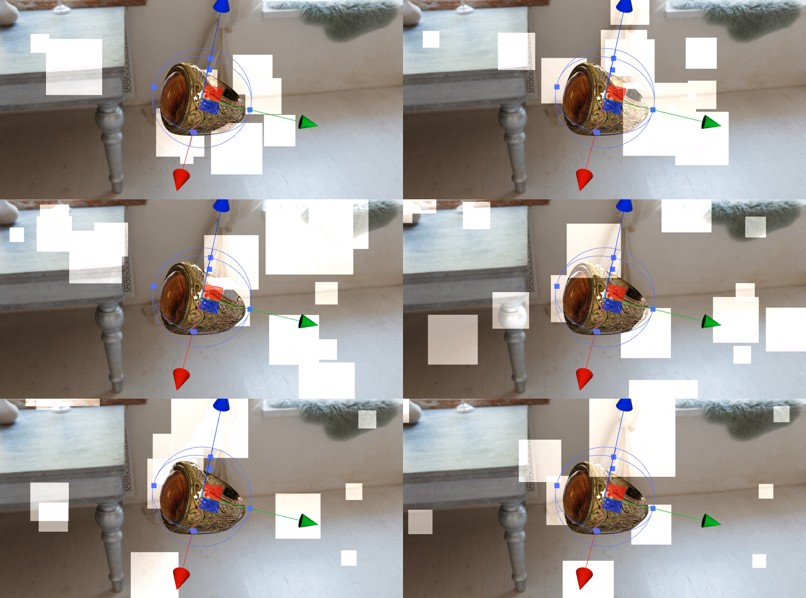
The effect we want is for the starlight to flicker on the model’s surface, and the particles shouldn’t fly off after spawning. Recall the details of the parameters we mastered during the smoke-making process above: StartSpeed is set to 0.
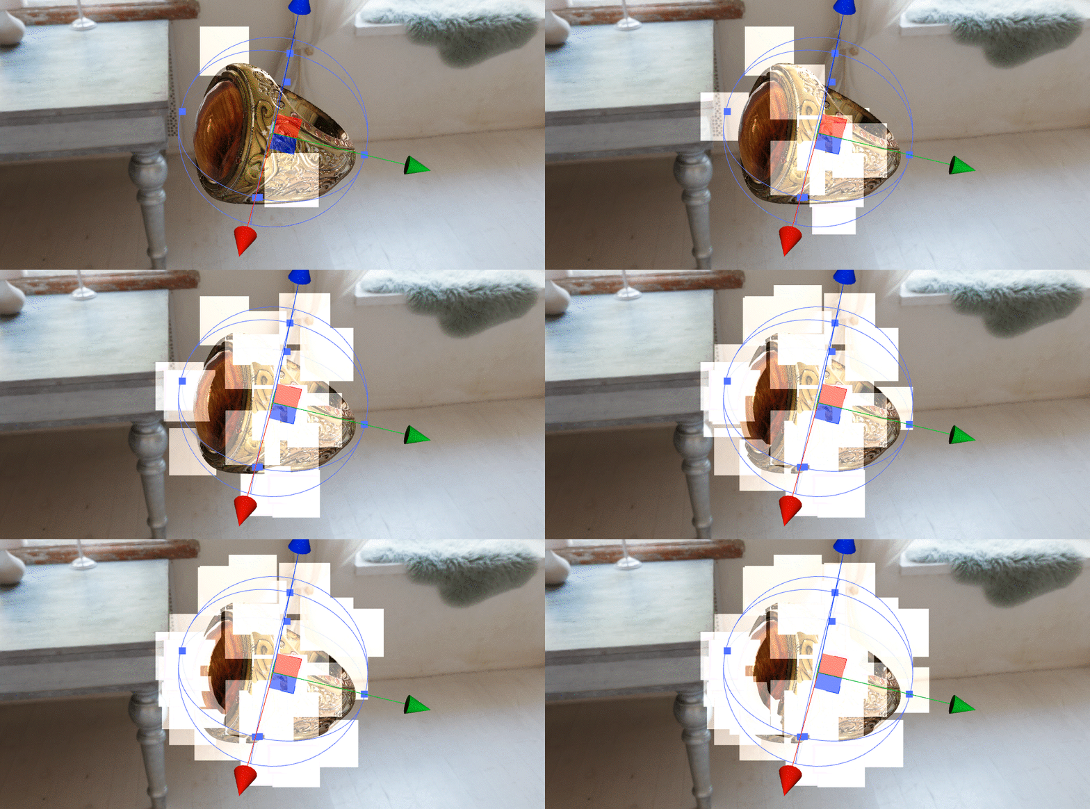
When StartSpeed is 0, the particles will not fly out after spawning but will stay where they were born. To ensure that particles are only generated outside the emitter, you can also select Shell under the EmitFrom parameter under the ShapeModule module.
Particle materials can now be assigned to particle systems. Drag and drop the material that uses the sprite atlas to the ParticleMaterial parameter under the Render section.
The white squares of the particles turn into a bunch of dense highlights. We’ve mentioned this before: the particle material uses the “Add Alpha” blend mode by default, making it very easy to blend the black background’s mapping. The linear overlay also matches the linear overlay nature of light in reality. As for why it’s a dense highlight, it’s not hard to understand: the sprite atlas looks like a dense stack of decals on the surface. We need to get the particle system to recognize the sprite atlas as a dynamic effect.
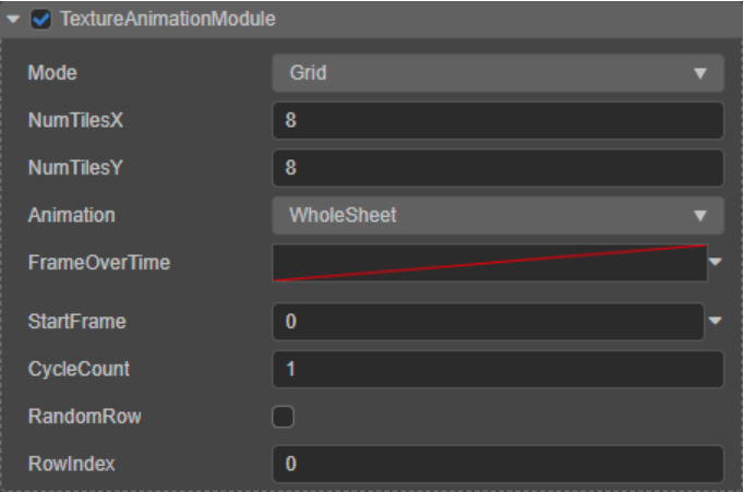
First, check TextureAnimationModule to enable the related module. A sprite atlas is a collection of image sequences, so you need to tell the module how it is assembled: look at the sprite atlas, note its number of rows and columns, and enter it into NumTilesX and NumTilesY.
Next, you need to make the sprite set move, which the FrameOverTime parameter will create. We mentioned the curve value of the parameter previously: the horizontal axis of the curve is the entire life cycle of the particle, and the vertical axis of the curve is the numerical value. Therefore, it is necessary to input a curve value for FrameOverTime, and the animation effect is achieved by the value of the curve. The easiest way is to use a straight line from (0, 0) to (1, 1), which means that each image sequence in the sprite atlas is set linearly as the particle lifetime goes by, which is the same as video playback.
So what if you use a straight line from (0, 1) to (1, 0)? This means that starting from the last image sequence in the sprite atlas, the previous image sequence is used linearly, and the effect is the same as the video played in reverse.
What if, instead of straight lines, I used bezier curves? The effect is also well understood: “Uphill” means forward sequence playback, “Downhill” means reverse order playback, and “Up/Downhill” amplitudes anything higher than 45 degrees meaning a higher than average use of frames (“Fast forward” effect), and vice versa means lower frame rate (“slow rewind” effect).
Now that we’ve told the module to “play” those image sequences and how to “play” them, we need to tell the module how many times to “play” it. Enter the value into the CycleCount parameter, if the value is 0, the sprite atlas will not play, and the particle will stay on the first frame of the sequence; if the value is greater than 1, the particle will play the corresponding number of times during the life cycle.
After completing the settings, we successfully imported the effects created by After Effects into Cocos Creator as particles in the form of image sequences and the medium of a sprite atlas. You will notice that the playback speed of each starlight seems to be a little slow: the animation is only two seconds when exporting the image sequence. The reason for this was mentioned earlier: the particle will use its entire cycle to play the image sequence, which is equivalent to stretching or shortening the animation in the sequence to the same length as the particle’s life cycle. We just need to change the particle’s lifetime accordingly (StartLifetime) or increase the number of times it is played in the lifetime (CycleCount).
Finally, add some randomness in size and rotation to the particles, using the other mods you learned during the smoke-making process. The final effect looks similar to our video example.
In theory, any animation effect can be exported as an image sequence with an alpha channel and then imported into Cocos Creator through sprite atlas.
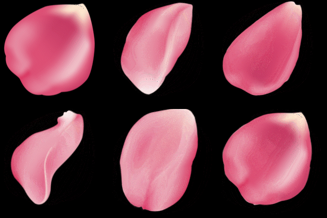
So TextureAnimationModule modules can also be used to create various other effects. For example, if we want to create a flower petal effect with particles, and we want the petals to have more movement and flip during the process of falling, but using a 3D petal model is a bit rigid, we can create a 2D petal transformation animation first, and export the image sequence to a sprite set to be used as particles for each petal. This replaces the 3D particles with 2D particles, thus giving more performance space and giving the artist the freedom to determine the various poses of the petals.
Rain (3D Particles)
rain final effect
Whether it’s smoke or starlight, they’re the illusion of 3D effects achieved by exploiting 2D assets. So, is it possible to use real 3D models as particles? The particle effect of the rain that we will make below requires a 3D model as a particle to achieve.
The final effect requires two separate particle systems: the raindrops falling in the air and the water splashing on the ground. At present, the Sub-particle system is not supported in Cocos Creator. That is to say, we cannot start the emission of another particle system at the position where the particles of one particle system fall. However, this does not affect our production of more satisfactory rainfall effects.
The presentation of liquids is usually a headache, but we can start with the materials of raindrops and water splashes.
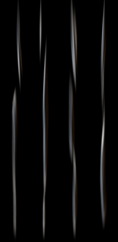
In reality, falling raindrops are highlighted due to light refraction, so raindrops usually appear brighter than the scene in the background, especially when viewed from a backlit angle. The material of the raindrop particles is relatively simple. We only need to make a map of the raindrops in flight and create a difference in brightness with different Alpha blending modes of the material. Although the raindrops have their own shape when flying in the air, we don’t need to pay special attention because no matter what kind of rainfall effect, the raindrops will only pass in front of our eyes instantly. In addition, due to the influence of dynamic blur, the raindrops in flight can be abstracted as a slender column. We just need to give it a little thickness to make sure the refraction highlights are visible.
In this case, the texture of the raindrops is easy to draw: use the brush tool in Photoshop and draw a few white vertical bars. If you are looking for details, you can add some small circular protrusions to the vertical bars to simulate the feeling of raindrops gathering into a stream. Finally, you can also add a layer of radial blur to the drawn vertical bars to simulate the motion blur effect when falling.
However, just relying on a few falling vertical bars may be too monotonous. Combined with the splash effect of raindrops falling on the ground, the feeling of rain can be made more convincing.
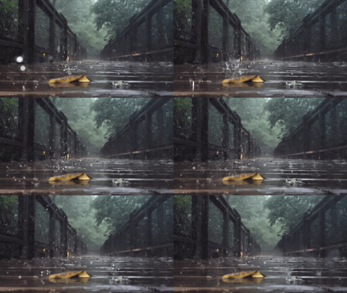
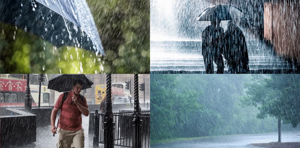
It can be observed from the reference: when the raindrops fall on the ground, they will splash a similar cylindrical spray, and then the spray will collapse from top to bottom, and the cylindrical spray will gradually become a cone with a large top and a small bottom. Until it completely collapses into a plane and merges with the ground.
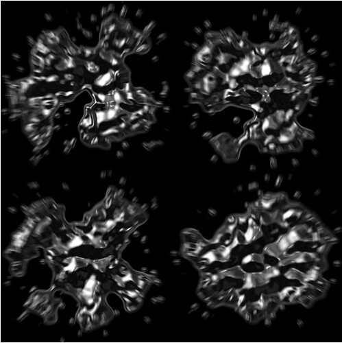
Since we need the splash effect, we can collect some splash materials. In the same way as raindrops, the color and precision of the material are not necessary. Only the shape of the water splash is needed. Apply the process we did when making the smoke, decolorize the material, level it, and finally add a layer of a radial blur. After all, splashes, like raindrops, only flash briefly before our eyes.
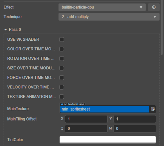
After the textures are made, import them into the engine to make particle materials. We’ll use the GPU Particle Material this time: open the Effect parameters drop-down menu and select builtin-particle-gpu.
Raindrop’s particle system is straightforward: turn on the ShapeModule, select the box-shaped emitter, and rotate the emitter 90 degrees to emit vertically downwards. Move the parent node of the entire particle system to a position with a higher vertical height, adjust the flight speed (StartSpeed) to make the particles fly at a speed close to the falling of raindrops, and adjust the life cycle (StartLifetime) so that the particle life cycle ends when it roughly falls to the ground.
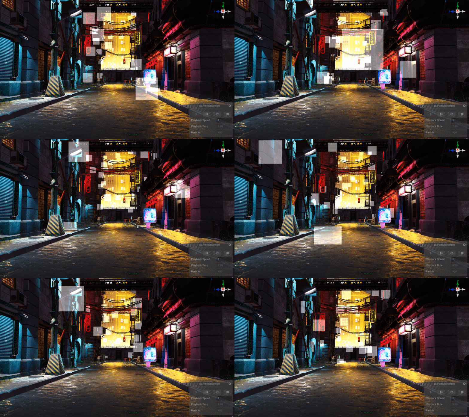
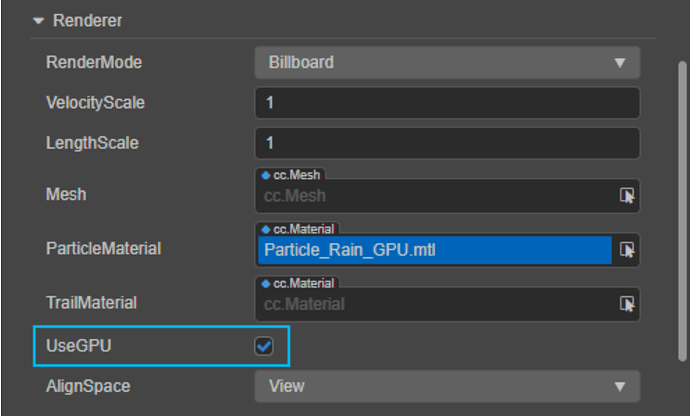
Since the particle material we created for raindrops is suitable for GPU particles, the particle system needs to check the UseGPU parameter.
GPU particles are more efficient than the normal particles we used before. Considering the use of 3D models, we chose to use GPU particles when making rain effects. However, all implementations of the rain effect can be achieved using ordinary particles.
Go back to the raindrop map, and you will find that this is actually a sprite atlas, which contains four raindrop maps. However, these four textures are not a sequence. They do not constitute an animation. We want the raindrop particles to choose one of these four textures to use randomly. So, how can this effect be achieved?
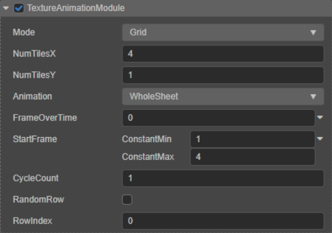
Open the TextureAnimationModule module, which we used in the process of making starlight to create the function of a sprite atlas animation, and also used it to let particles randomly select a sequence in the sprite atlas as a static map. We still need to tell the TextureAnimationModule how the sprite atlas was assembled, by entering the number of rows and columns of the sprite atlas in NumTilesX and NumTilesY, respectively. Since the animation effect is no longer required, it is no longer necessary to give the FrameOverTime curve a value and let it keep the default constant value at 0. StartFrame controls the starting frame of the animation.
Since there is no animation effect, the particles will still be at the StartFrame. Remember our trick to make random effects using max and min values? In the same way, you can set the maximum frame value and the minimum frame value for StartFrame, and let the particle system randomly select frames in it (note: the minimum frame number is 1, not 0). Finally, we still need to enter a value for CycleCount, because although there is no animation, the particle system still needs to cycle through all the sequences in the sprite set to randomize the frames.
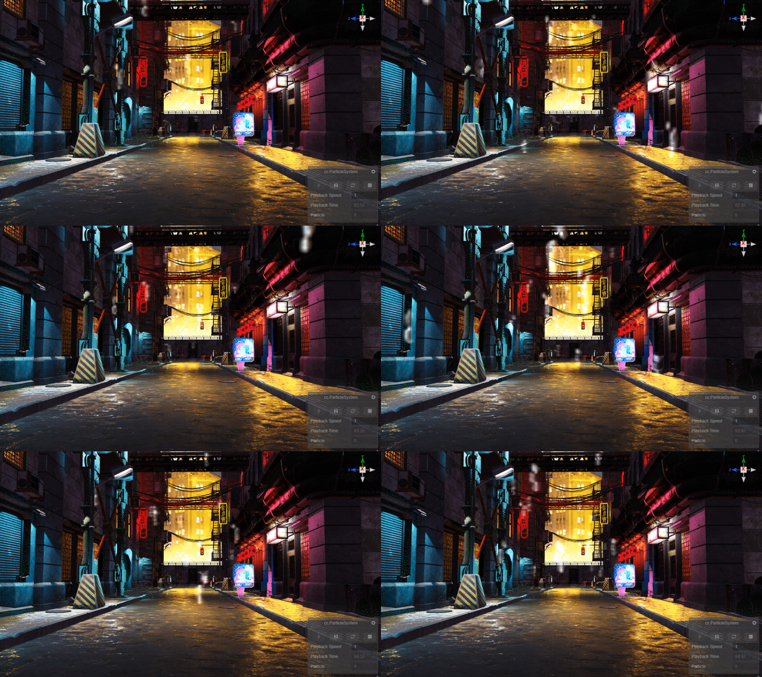
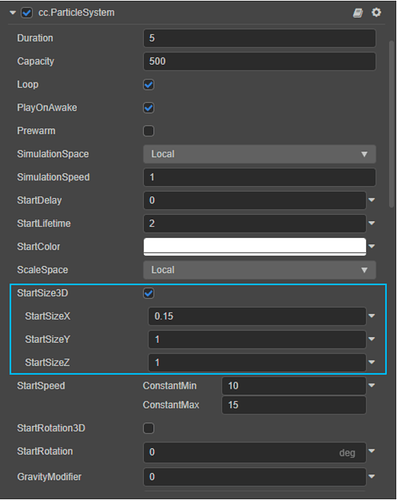
The random frame of the raindrops is available, but the texture of the raindrops is very severely stretched. This is because the rain map is not a square. The particles in Billboard’s render mode will stretch the map to a 1:1 aspect ratio. To fix this, we can use the StartSize parameters.
By default, the StartSize module controls the particle size isometrically. We can check StartSize3D and enter values in the StartSizeX, StartSizeY and StartSizeZ axis, respectively, and scale the particles to the ratio that matches the raindrop map.
With that problem solved, Billboard has another problem: Billboard is always facing the camera. But we don’t want the raindrops to fall in the scene always facing the camera: when we look down, the raindrops should sweep longitudinaly from our viewing angle and not still a vertical line. So, Billboard is no longer suitable for raindrop particles, and we need accurate 3D models for raindrop particles.
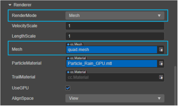
Selecting the RenderMode parameter Mesh will cause each particle to be emitted as a 3D model. Then, choose the model to use in the Mesh parameters. We can drag and drop any mesh file imported into the model into the Mesh parameters. Here a simple patch will do the trick so that you can use the engine’s built-in quad model quad.mesh.
Although the 3D model is used as a particle, each particle that is generated still faces in one direction, and we also need to make each particle receives a random rotation value when it is born. The StartRotation parameters we have used before are similar to StartSize. Check StartRotation3D, enter values for StartRotationX, StartRotationY, and StartRotationZ, respectively, or use the maximum and minimum values to define a random range.
Back to the particle material of the raindrops: Add mode is still too strong for raindrops. In the Technique parameter, select 2-add-multiply. In this mode, the pixels of the particles will first be linearly multiplied by the pixels in the Frame Buffer (equivalent to positive overlay in Photoshop). And then linearly add to the pixels of the Frame Buffer. This allows the particles to brighten the scene while mixing the colors in the scene, more closely highlighting the effect produced by raindrops refracting light in the environment.
Finally, adjust the frequency of particle emission (RateOverTime) according to the intensity of the rainfall we want to achieve, adjust the rotation parameter of the parent node to introduce a certain slope for the rainfall, and the raindrop part is completed.
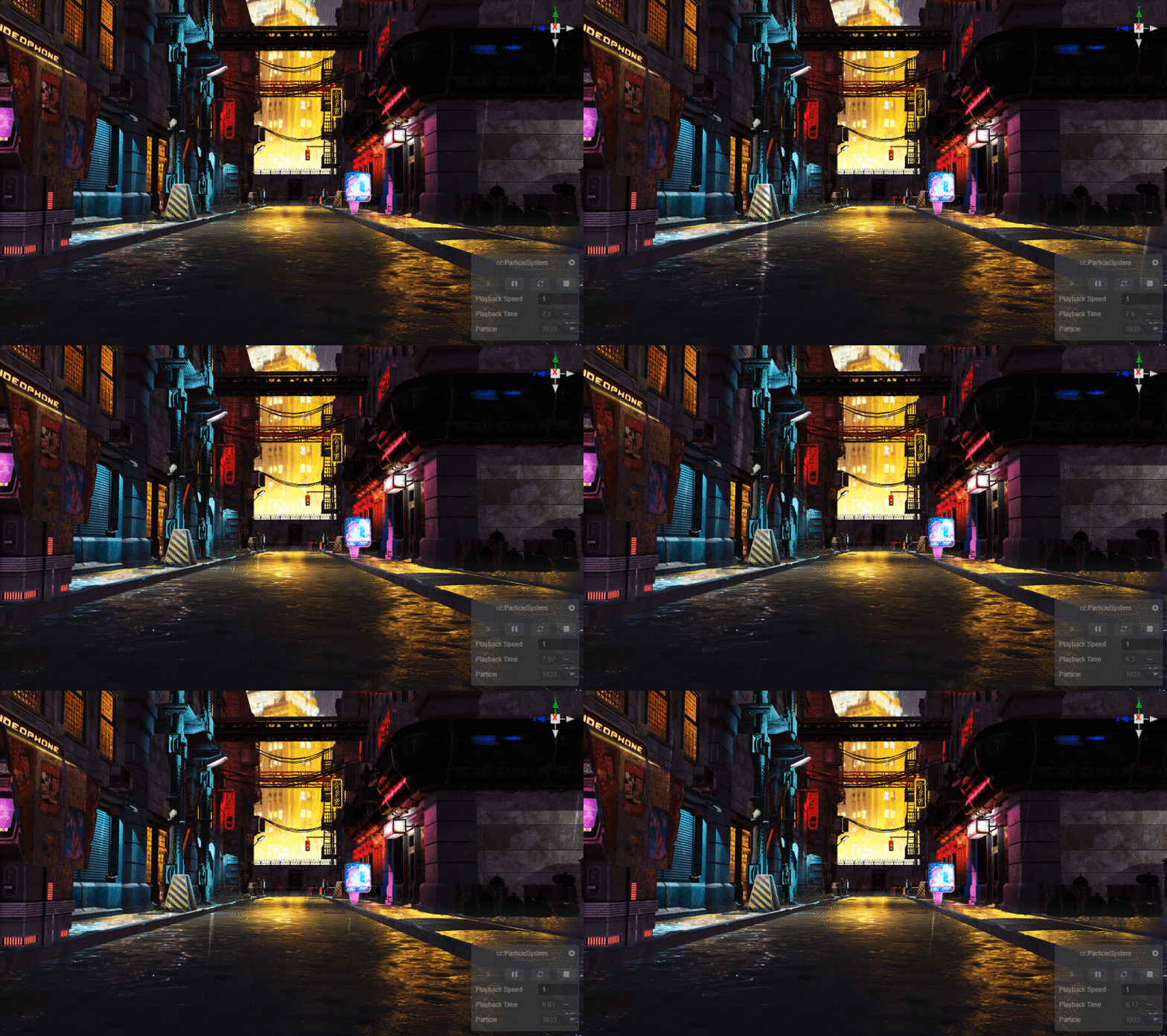
Next, we need to make the splashes on the ground. Make a copy of the parent node of the raindrop particle and move it to a position close to the ground. Splashes stay on the ground and don’t fly outward like ordinary particles. We have dealt with a similar problem in the process of making starlight. Set the StartSpeed to 0.
In the ShapeModule module, give the square box emitter a small Scale value for the Z-axis. We want to get a box-shaped emitter with a very fine thickness, which will provide a fine height variation to the emitted particles.
We have already used a 3D model as a particle when creating the rain, and there is no doubt that the particle for the water splash also requires a 3D model and, more importantly, that this 3D model is capable of implementing the changes from columnar, to conical, to flat as observed in the reference. Since the particle system can only accept mesh files as 3D models, animating them in DCC is obviously not feasible. The splash shape change can only be achieved by using the rotation and size modules that have been used before.
Since the particle system can only accept mesh files as 3D models, animating them in a DCC is obviously not feasible. The splash shape change can only be achieved by using the rotation and size modules that have been used before.
So, what kind of model do we need?
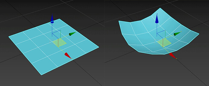
Since we already have the mapping of the water splash, we can start with a face piece: create a new simple face piece and give it a certain amount of mesh density. By bending and deforming the plane, modify it to be raised at the corners and depressed in the middle. Make sure that the anchor point (Pivot) of the model is in the center of the depression, so that the model will start deforming from the depressed part.
Import the model into the import engine and drag the mesh file onto the Mesh parameter.
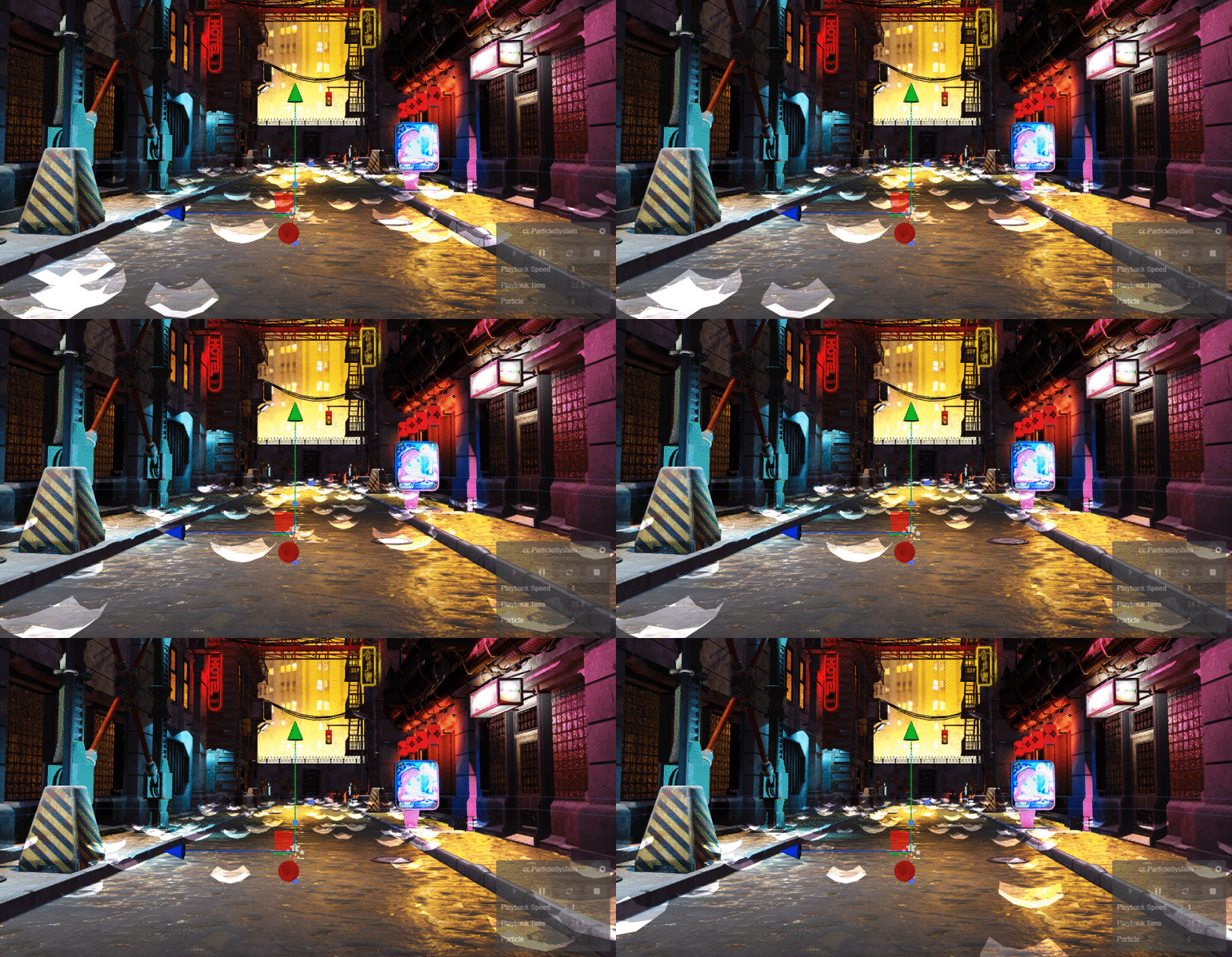
First, apply the splash map to the model. The splash map also contains four different variations. We can use the same method we did for raindrops, using the TextureAnimationModule module randomly taking frames.
There is a reason why a face piece with protruding corners and a depressed center was chosen as the model for the splash: if the facepiece is enlarged in the vertical axis direction, the corners of the model are pulled up and take on a cylindrical-like form; conversely, when it is reduced in the vertical axis direction, the corners of the model are then lowered, and the depression in the center remains the same, making the whole closer to a cone. When the value in the vertical axis direction reaches 0, the four corners no longer differ from the center in the vertical position, and the cone becomes flat. So, the different forms of the water splash can be achieved by resizing the model in the vertical axis direction with the aid of coordination in the other axes.
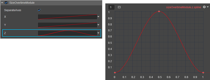
We have already used the SizeOvertimeModule module. Check SeparateAxes, and modify the size on the X, Y, and Z axes, respectively. First of all, we need an effect of the overall blooming of the spray. Through the previous understanding of the curve value: you can input a straight line from (0, 0) to (1, 1) on the X, Y, and Z axes, respectively, to achieve the spray from small to large. Fade out effect. What we need is that the water blooms and then collapses into a plane, so we need to make some modifications to the curve on the vertical axis: right-click at about the middle of the curve and select Create keyframe to create a new node on the curve. With the new node, you can drag the node at the end of the curve to the position where the vertical axis is 0, thus forming a triangle curve. Select all the nodes on the curve, in turn, right-click to select Interpolation Mode → Cubic, and interpolate between the nodes to obtain a bell-shaped curve.
Using the action of the SizeOvertimeModule module, the animation effects of water bloom and collapse have been created.
However, this is not the final result: the current size of the spray is a bit too large, and it is not nearly cylindrical enough when it first blooms. If we continue to adjust the SizeOvertimeModule curve through, it is difficult to see the corresponding results intuitively and may destroy the existing animation effect. Remember StartSize parameters? We used it to change the size of the raindrop Billboard indiscriminately to adapt to the raindrop map. Now we can also use it to adjust the overall size of the water splash: check StartSize3D, and assign a value on the X, Y, and Z axes, which can create an ideal The water splash form will not affect the animation effect that has already been done.
Finally, as before, adjust the emission frequency and life cycle of the particles (this will affect the speed of the splash animation), and the splash creation is complete.
Flames (composite particle)
fire final effect
When we use particle systems to create an effect, in reality, we often find that just using a single particle system is not enough. Various effects are usually a combination of multiple factors. Visually restoring these details is often more effective than constantly polishing a single particle system. In the following examples, we will use various systems to achieve the effect of fire.
First, you need a sprite atlas of flames. The flame atlas we used was made with procedural textures. The production of procedural textures generally follows the same logic: normal geometry → deform the geometry with different types of procedural noise textures and then use different alpha blending modes to overlay different deformation effects → use the parameters of the procedural noise texture to displace the noise and thus animate the deformation → use a gradient color according to the brightness.
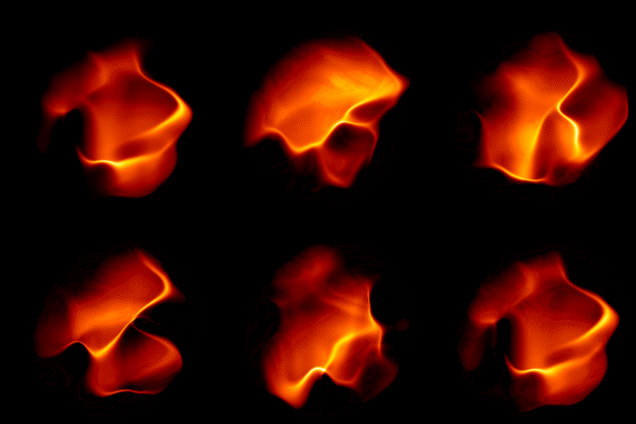
After exporting the image sequence, follow the previous process to convert the image sequence into a sprite atlas. Import the sprite atlas into the engine and make corresponding particle materials. The default Add mode of particle materials is very suitable for fire production.
For the particle system, select a cone-shaped emitter, set the Angle and Length parameters to 0 so that the emitted particles will not scatter outward, and ensure that the particles are all emitted on the same horizontal plane. The flame particles should be arranged densely and rise at a rate slightly lower than that of the gas, but the flame can only rise to a certain maximum height, indicating that the life cycle of the particles is relatively short. Therefore, a value slightly less than 1 for StartSpeed can be taken, and a smaller value for StartLifetime is also required.
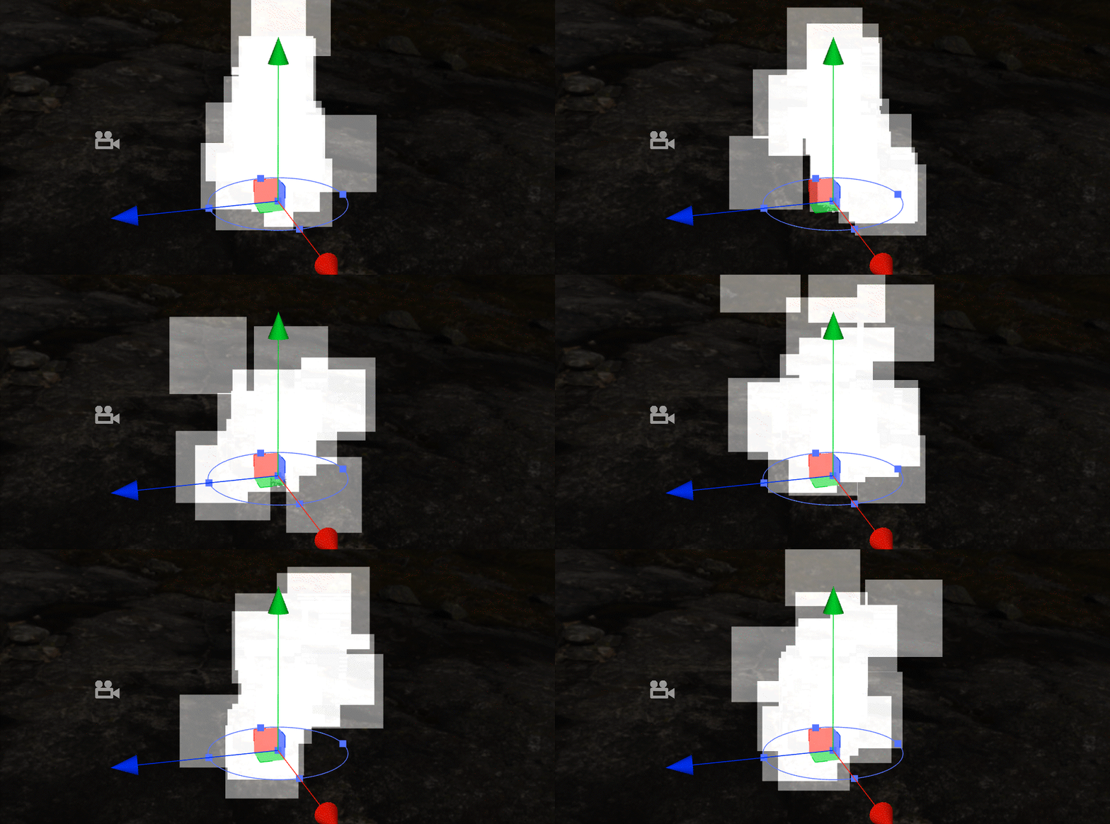
Flames generally appear to be overall bell-shaped, which means that particles are relatively large in size when they are first fired and gradually decrease over their lifetime. Most of the particle cases we’ve encountered before have been “uphill” curves that are small at launch and progressively increase over their lifetime. For flames, a “downhill” curve can be used in the SizeOvertimeModule module.
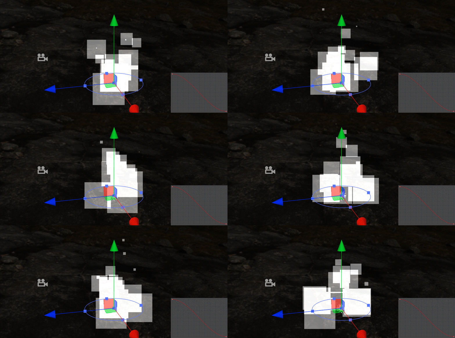
Assign the material to the particle system, and open the TextureAnimationModule module. We have used the Curve and TwoConstants value types before. TwoCurves is a combination of the two: the particles will randomly take a value between the values of the two curves at a point in time in the same life cycle. We can set the FrameOverTime parameter to TwoCurves type and give it an “uphill” curve and a “downhill” curve. The result is that some particles play the sprite atlas in positive order, some play in flashback, and some take two median values. We’ve also used the StartFrame parameter, which determines the start frame of the sprite atlas playback, using a maximum and minimum value to let the particles randomly choose a frame from the atlas to start playing.
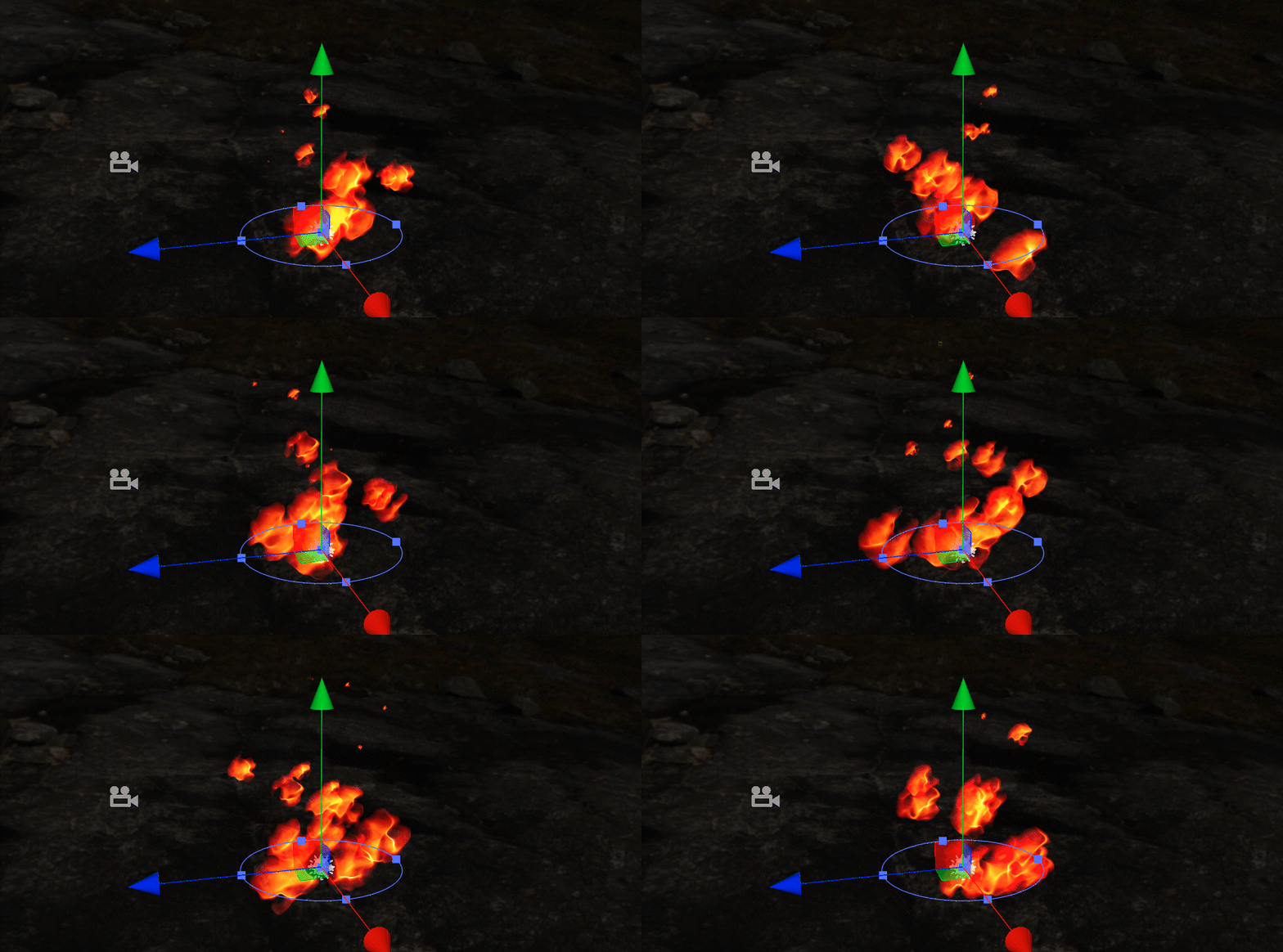
As with smoke, you can use the ColorOverLifetimeModule module to hide the particles that are just emitting and disappearing using an alpha value, making the overall shape of the fire smoother. Using the RGB values in the gradient, you can fine-tune the color of a certain interval of the flame to enrich the color and brightness of the flame.
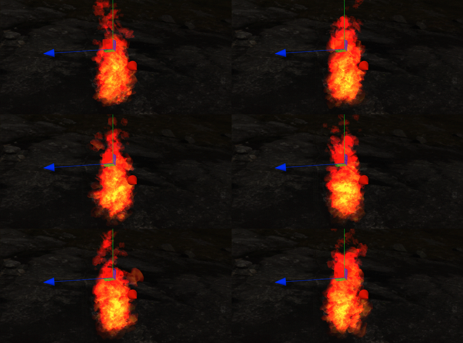
The flight path, randomness, and overall shape of the particles are all there. We just need to adjust the frequency and density of the particles as before, add some randomness of rotation and size, and the effect of the flame will be achieved.
For many projects, the flame-making ends here. However, even though our particles look more like fire, they still have a fake feel when placed in the scene alone. In this case, we do not need to consider increasing the complexity of rendering and pursue a higher number of particles. On the contrary, we can create some details that will accompany particles in reality, such as the generation of smoke accompanied by the fire, there will be incompletely burned sparks flying out; when the rainfall is relatively intense, a thin layer of water vapor forms near the ground, etc.
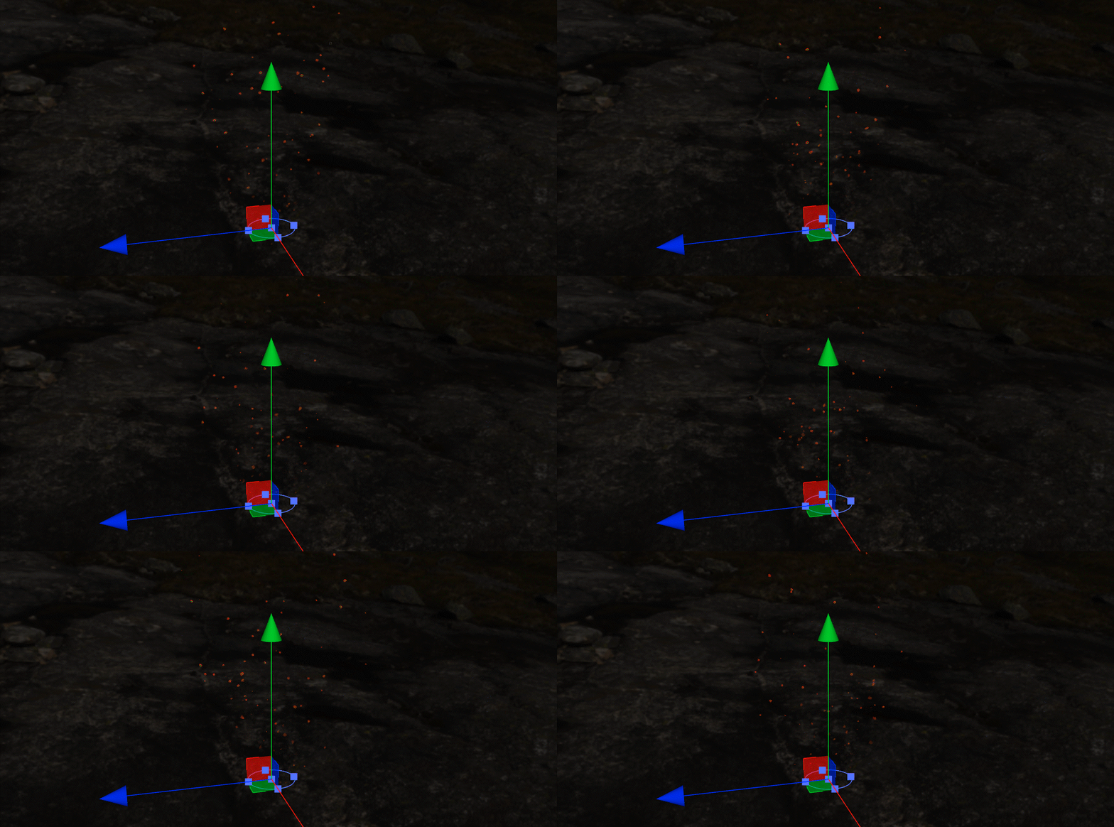
We have completed the production of smoke, and the production of sparks is not complicated: the atlas of the flames is already available, and we only need to make particles that conform to the flight laws of sparks.
We will modify this basis of the flames to achieve the effect of sparks. Make a copy of the flame particle system, and sparks can continue to use the flame sprite atlas. We can slightly adjust ColorOverLifetimeModule gradient color to make it more vivid.
The most significant features of sparks are:
-
If the size is small, the value of the
StartSizeparameter orSizeOvertimeModulemodule should be relatively small but still visible to the naked eye; -
The flight trajectory is different. Sparks are small solid particles with incomplete combustion. It should not gather together like a flame. On the contrary, it should tend to fly out under the action of thermal energy. Affected by its quality after flying out, there should be a downward trend.
The cone emitter we choose when making the flame itself emits particles in the direction of the cone, and we only need to restore the Angle parameter to a specific value to give the cone a certain angle.
The RandomDirectionAmount, RandomPositionAmount, and SphericalDirectionAmount parameters at the bottom of the emitter properties we introduced earlier can add random changes in position and direction to the emission of particles. In addition, in reality, some sparks can be ejected very high, and some can only fly to a lower altitude. This difference is the difference in the flying speed of the particles, which can be easily realized with the StartSpeed parameters. Finally, we need to make the kinetic energy of sparks fall under the influence of gravity. In the process of making the smoke, we used the ForceOvertimeModule module to provide the kinetic energy change for the floating of the smoke. There is a convenient GravityModifier parameter in the basic parameters of ordinary particles, which can give gravity properties to the particles. When its value is equal to 0.98, the particle will fall directly to the ground after being emitted like most objects in reality. So we just need to give sparks a very small GravityModifier value so that they can fly while maintaining the kinetic energy affected by gravity.
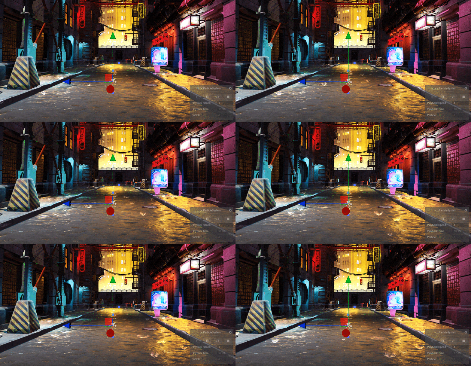
After the sparks are made, put the flames, sparks, and smoke in a group and place them in the scene. Of course, don’t forget to put a fiery red spherical lamp to illuminate the flames. After doing this, has the credibility of the flame improved a lot?
Spitfire and Candlelight (Variants of Particles)
We have completed a complete flame particle system. However, although there are many places where flames are used in the project, there are still limited opportunities to use a bonfire that is upright. What if we need to make other forms of flames: like jet flames or candle flames?
fire-breathing final effect
The sprayed flame looks complicated, but it is no different from the particles we have made before: the first is the shape. We are very familiar with controlling the particle emission speed, density, particle size change, and other factors. In fact, we have already answered to a certain extent how to make this kind of spewing flame: when making a bonfire, based on the experience of producing smoke, we give SizeOvertimeModule a “downhill” curve to make the particles smaller with the life cycle, and now we only need to Conversely, giving SizeOvertimeModule an “uphill” curve can get the flame particles that expand continuously after emission, which is the same as the size control of the smoke particles. The strong kinetic energy of the flame jet can be interpreted as the speed of particle emission, so StartSpeed is still the best choice.
The smoke produced by the jet should float upwards into the air because of its lighter mass. We are already familiar with controlling the particle’s flight trajectory after emission, and ForceOvertimeModule will help us achieve its effect. We introduced the GravityModifier parameter when we created sparks. Setting GravityModifier to a negative value can also get the effect of anti-gravity, causing the particles to float into the air. In addition, the VelocityOvertimeModule module can provide a specific numerical and directional addition to the particle emission. If you need a certain degree of resistance to ForceOvertimeModule and GravityModifier can be turned on to influence the particle flight.
In contrast, the LimitVelocityOvertimeModule module can provide a counterweight to the VelocityOvertimeModule, prioritizing particles at the end of their lifecycle. Used in conjunction with the VelocityOvertimeModule, this allows us to make transitions where the particles are first affected by the jet’s kinetic energy. The kinetic energy is exhausted, and the particles are only affected by gravity and the ForceOvertimeModule.
As for the sparks, after the ejection, they will first follow the direction of the ejection, but due to the influence of the smoke, its tendency to fall to the ground is not apparent, but part of it will be carried into the air by the smoke. Using the above modules, we can also specify the flight force and trajectory of the spark.
Finally, it ColorOverLifetimeModule is still an essential part of the overall presentation of the particles. We can adjust the color of the left side of the gradient, the part of the particle that just shot out, to make it appear a blue-green color, simulating the color of the flame of some chemical components at extremely high temperatures. Not only does the color change, but the alpha value of the flame is also very important. The flame particle material uses the Add mode. We can try to add darker color nodes to the gradient to make the alpha value more natural while producing color changes.
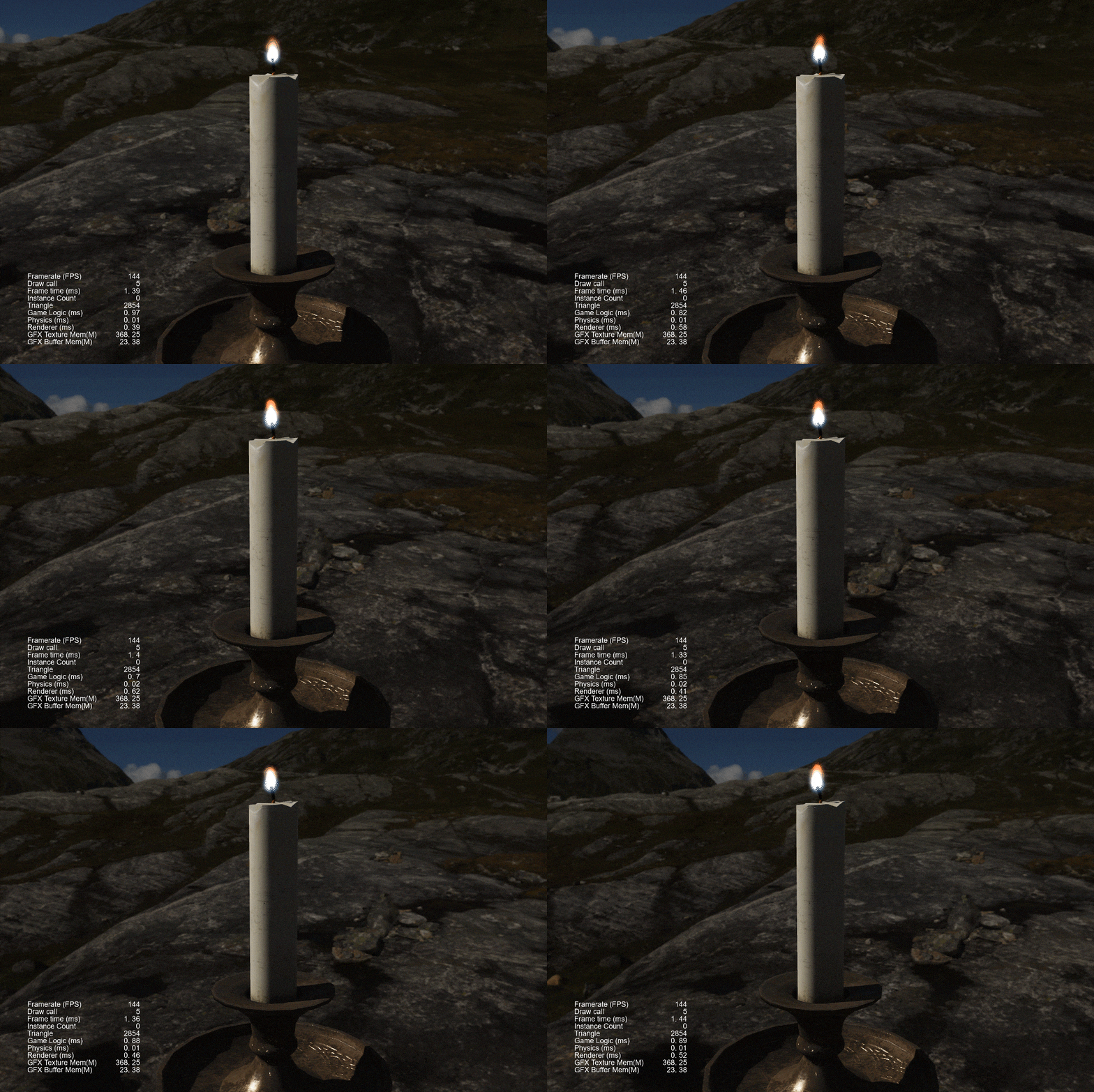
Candlelight final effect
Compared with the intensity of fire-breathing, candlelights are easier to build. In some projects, even the reduced version of the bonfire is directly used as a candle. Although theoretically, there is no difference between candlelight and an ordinary bonfire, from a visual point of view, candlelight has its unique characteristics:
-
The color is brighter, only the tail will show some fire red, and the main part is almost white;
-
The overall shape is relatively uniform, there are no complex shape and detail changes, but it still has a sense of jumping flames;
We can still use the scaled-down bonfire as a starting point. First, since the candle flame has a more consistent form, there is no need for the sprite atlas of the flame to make an appearance. Use a static circular gradient directly, or select the Default-Particle mapping that comes with the engine in the drop-down menu of the MainTexture material parameter. Now that a circle texture is used, the change in the particle rotation is no longer necessary. Compared with candles, there are many tiny flames at the tail of the bonfire. We have been using ColorOverLifetimeModule to hide the particles at the head and tail.
Similarly, we can be more aggressive when using ColorOverLifetimeModule, and further expand the hidden range to the tail of the bonfire. The result is a seamless candlelight outline. Finally, the color change of the candle can also be achieved with ColorOverLifetimeModule, which can be used when making the fire: The left side of the gradient is set to blue, and the right side is set to fire red, which are the head and tail of the candle, respectively. A clear and clean candle flame with color changes is complete.
Today, through the particle system of Cocos Creator, we have realized the particle effect presentation of smoke, starlight, rain, flame, fire, and candlelight and introduced the main functional modules and production methods in the particle system. You will find that although various effects in nature seem to be fickle, there are specific rules to follow. We can create various convincing particle effects by adding random changes and superimposing a certain number of particles.
